
Dense fluid spray cleaning process and apparatus

a technology of fluid spraying and cleaning process, applied in lighting and heating apparatus, combustion types, manufacturing tools, etc., to achieve the effect of improving the performance of liquid phase c02 conversion, improving cleaning performance, and adaptability and versatility

Active Publication Date: 2008-11-18
HITACHI HIGH-TECH CORP
View PDF11 Cites 33 Cited by
  • Summary
  • Abstract
  • Description
  • Claims
  • Application Information

AI Technical Summary

Benefits of technology

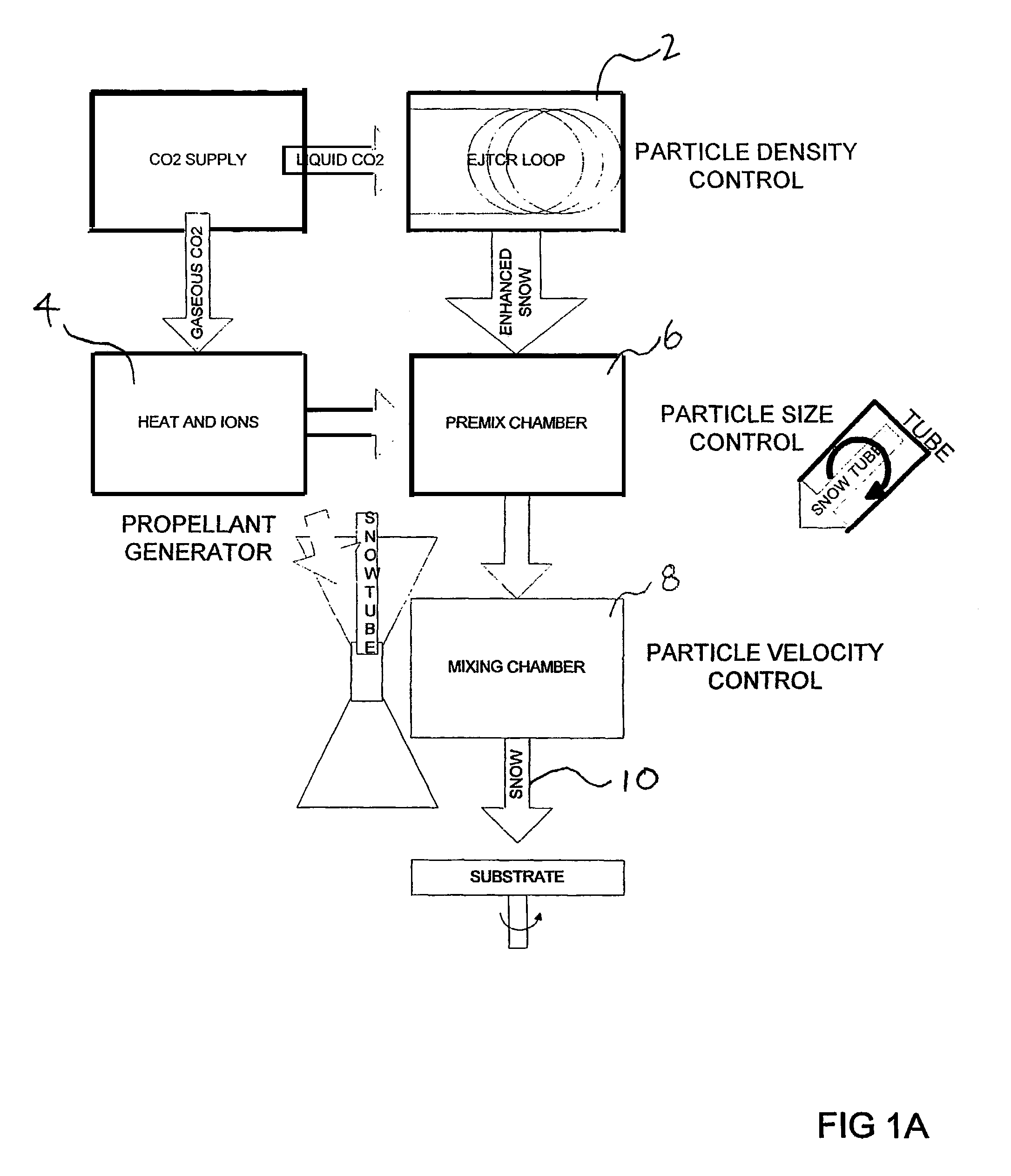
[0057]There have been many patents issued, and in this decade particularly, for solid-phase cleaning devices and processes. None employ a coaxial momentum transfer mechanism using thermal-propulsion control of particle velocity and size described herein. Improved coaxial dense fluid spray cleaning processes and apparatuses have been developed and are described herein which greatly improve cleaning performance, operational characteristics, adaptability and versatility over U.S. Pat. No. 5,725,154 by the present. Most importantly, the present invention significantly improves the performance of conversion of liquid phase C02 to solid phase and control of particle size and velocity.
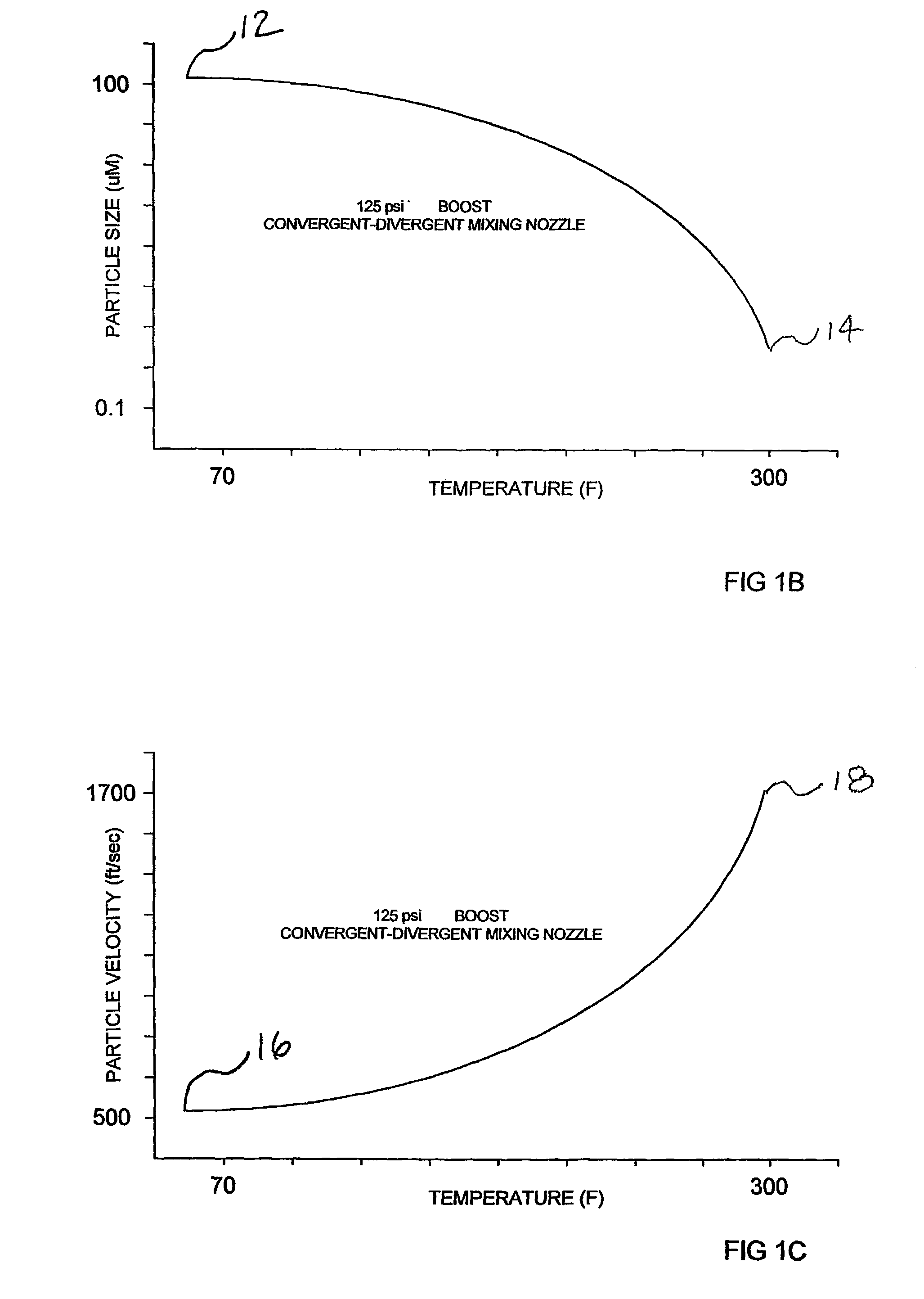
[0059]The present invention changes temperature and pressure of an inert optionally, ionizable propellant gas over a wide range of temperatures from 70 F to 300 F and pressures from 30 psi to 10,000 psi—this changes the physicochemical and kinetic characteristics of an enhanced snow particle mass generated within a condensor tube located at the center of a coaxial delivery system. Particle size, density, apparent hardness and velocity of a stream of condensed carbon dioxide can be precisely controlled by altering the temperature and pressure of the propellant in combination with altering the length of enhanced condensation tube which supercools and condenses precisely injected amounts of liquid carbon dioxide. An enhanced solid particle-gas mixture is produced prior to combining with condensation tube and propellant gas tube assemblies within a coaxial delivery line. A device called an Enhanced Joule-Thompson Condensation Reactor (EJTCR), containing a coiled or looped reaction tube having various lengths and diameters, is used to produce and densify a mixture of solid carbon dioxide particles (Enhanced Snow) from a source of purified liquid carbon dioxide. The EJTCR loop is thermally insulated and grounded and is comprised of various lengths and inside diameters of polyetheretherketone (PEEK) tubing. Because most of the condensation and sublimation heat transfer occurs within the EJTCR loop, the result is improved efficiency of the initial condensation reaction process. A propellant stream comprising pressurized, heated, inert and optionally ionized gas is produced in a separate subsystem. Purified inert gases such as carbon dioxide (preferred), nitrogen and clean dry air are heated using an in-line heater, filtered and ionized using an in-line DC ionizer assembly.
[0061]The efficiency, in relation to snow mass generated and cleaning energy performed, of the present invention is increased substantially over conventional Type I snow cleaning designs. Moreover, the present invention produces excess heat remaining following transfer, mixing and spraying operations, in accordance with the Carnot equation, which provides simultaneous local environmental control through inerting and thermostatting phenomenon.
[0063]The present invention further teaches a method of adding liquid and gas phase additives an enhanced condensation tube which are mixed and dispersed within the dense solid phase prior to injection and mixing within a nozzle. This provides improved physicochemical characteristics of the resulting spray cleaning agent such as improved contaminant solvency and lower tribocharging upon contact with a substrate.
[0071]Another aspect the present invention is the addition of solid abrasives to the propellant gas supply. Mixing solid abrasives with the dense snow mass provides an improved microabrasive finishing of substrates—cryogenic microabrasive finishing. The snow spray embrittles surface features such as burrs during simultaneous impingement of abrasive snow additives. The surface features of the substrate become harder at a lower temperature than the subsurface—therefore surface finishing is aided through an increase in hardness (less rolling and rounding of edges and burrs). Following this the spray is used to remove residue dusts and residues from the finished substrate.
[0072]Finally, the present invention discloses a cleaning system and system software for utilizing the various examples described above in a closed workcell using a centralized multi-axis programmable robot operating in a circular workcell pattern and using various stations having increasing particle cleanliness. This embodiment teaches the use of various robot hand tools—pick and place tool in combination with a cleaning tool, cleaning-laser tool, cleaning-inspection tool, or cleaning-ionization tool. Substrates are first picked up using a pick and place tool and moved from a dirty loading zone into a cleaner process zone. The robot then changes hand tools, placing the hand tool in a cleaning fixture for subsequent cleaning, and picks up any one of several novel snow or snow-process robots tools. Following robotic cleaning and / or processing, the robot cleans the pick and place tools critical surfaces, and replaces the cleaning tool with the newly cleaned pick and place tool. The cleaned substrate is picked up and placed in a still cleaner unload zone. The combination of a zoned workcell with a programmable robot, software and novel cleaning and cleaning-production tools provides an economical, versatile and adaptable cleaning and production tool.

Problems solved by technology

However, Type II equipment and operational costs are significantly higher than Type I systems.
Disadvantages associated with these mechanical designs include:1. Fixed spray pattern.2. Non-interchangeability of applicator designs (fixedhandheldrobotic).3. Bulky configurations.4. Uncontrolled tribocharging (electrostatic buildup) of non-metallic substrates such as plastics.5. Rapid localized substrate cooling and subsequent deposition of contaminating residues.6. Ineffective deep hole cleaning.7. Expensive equipment costs.
Type I applicators must have an expansion valve located close to the nozzle and the nozzle must also be very close to the substrate to effectively remove residues.2. Entrainment of ambient air which often contains moisture, particles, and other contaminating residues which condense onto surfaces which have been supercooled by the snow particle / gas stream.3. Externally applied environmental control measures such as heated air and particle control hinder the cleaning performance and are applied so generally that localized condensation, particle entrapment, or tribocharging still occur.
This type of electrical charge build-up can be extremely damaging to microelectromechanical devices (or can induce latent ESD defects) and will cause a departiculated surface to become an attractor (magnets) of airborne particles following snow cleaning operations.
This technology is large and bulky and cannot be used to precisely clean small parts commonly found in the semiconductor, electrooptical and electronics markets.
To date, no effective technique has been demonstrated to accomplish this requirement.8. Type II applicators also suffer from being too aggressive (i.e., substrate damage), very noisy, bulky and too costly for most precision substrate cleaning applications.9. Conventional snow cleaning applicators do not lend themselves to integration with production processes such as stamping, welding, bonding, curing and abrasive surface finishing operations because of the aforementioned problems discussed above.
Conventional snow cleaning processes do not have a method for real-time analysis of cleaned surfaces to accept or reject a particular cleaning operation.
The problem with this approach is that flowing air induces contamination through introduction of humidified air and potential particles.
Moreover, the charges present within the structure of the cleaning agent are not reduced effectively using this technique.
Most prior art suffers from these typical drawbacks:Impossible to precisely control charges being delivered to a substrate—each substrate and atmosphere is different.The portion of a substrate being impacted by the sublimable cleaning agent is not affected by neutralizing ions—only the circumference of the snow spray is affected.Backside or nearby electrostatic charging due to electric fields is not affected by these techniques—electric fields pervade the materials creating complexly charged surfaces.
This process is line-of-sight and very short range.
The main problem with this approach is that the electrostatic charge and electrical overstress are not effectively controlled on non-conductive substrates.
However this method tends to, by itself, become a source of chemical contamination within the cleaning process.
Moreover, in cleaning quartz lenses, as well as many other non-conductive substrates it is difficult to control electrostatic charging of the quartz substrate during sublimable spray cleaning.
Quartz cannot be grounded and commonly used antistatic chemical agents contained in the cryogenic cleaning agent would leave stains during cleaning.

Method used


Image

  • Dense fluid spray cleaning process and apparatus
  • Dense fluid spray cleaning process and apparatus
  • Dense fluid spray cleaning process and apparatus

Examples


Embodiment Construction

[0103]The invention describes an improved adjunct separation mechanism which involves the formation of variable-geometry microscopic substances called “Snow Gels” comprised of trace organic surface residues (treated as solvents or solutes) dispersed in solid phase carbon dioxide particles (treated as a subcooled solvent-solute matrix). This mechanism is supported by solubility research performed by Myers and Prausnitz (M. N. Myers and J. M. Prausnitz, “Thermodynamics of Solid Carbon Dioxide Solubility in Liquid Solvents”, Ind. Eng. Chem. Fund., 4, 209,1965) in which they treat solid carbon dioxide (solid-state xenon has also been studied) as a subcooled liquid to determine cohesive energy values.

[0104]Solid carbon dioxide possesses electron acceptor (Lewis Acid) and molecular quadrapole moment properties which contribute to a hydrocarbon-like cohesion energy and complex forming ability with hydrocarbons. Solid carbon dioxide has a measured solubility parameter of between 23 MPa1 / 2 a...


PUM

PropertyMeasurementUnit
Diameteraaaaaaaaaa
Diameteraaaaaaaaaa
Diameteraaaaaaaaaa

Abstract

Disclosed is a dense fluid spray cleaning apparatus comprising a gas supply (3) for providing a predetermined amount of a gas to an enhanced joule-thompson condensation reactor (2) and for providing gas to a propellant generator (4), a premix chamber (6) for receiving a solid particulate from the enhanced joule thompson condensation reactor and heated gas from the propellant generator, and a mixing chamber (8) for receiving the solid particulate and the heated gas and producing a spray stream containing the solid particulate.

Description

BACKGROUND OF INVENTION[0001]Carbon dioxide exists as a low-density gas at standard temperature and pressure conditions and possesses phase boundaries with a triple point (Solid-Liquid-Gas co-exist in equilibrium like a glass of ice cubes and water) and a critical point (Liquid-Gas have identical molar volumes). Through pressure or temperature modification, carbon dioxide can be compressed into a dense gas state. The term ‘Dense Phase Carbon Dioxide’ is used herein to describe all phases of carbon dioxide: liquid state, supercritical state, dense gas state, and solid-state. These states have densities that are within the range of liquid-like or near-liquid substances.[0002]Compressing carbon dioxide at a temperature below its critical temperature (C.T.) liquefies the gas at approximately 70 atm. Cooling liquid-state or gas-state carbon dioxide to its freezing point causes a phase transition into solid-state carbon dioxide. Compressing carbon dioxide at or above its critical temperat...

Claims


Application Information

Patent Timeline
IPC IPC(8): F23D11/16F23D11/10B08B1/00B08B6/00B08B7/00B24C1/00H01L21/00
CPCB08B1/00B08B6/00B08B7/0092B24C1/003B24C1/083B24C11/005H01L21/67028H01L2224/85012H01L2924/01077H01L2924/3025H01L2924/01019B08B1/12
Inventor JACKSON, DAVID P.
Owner HITACHI HIGH-TECH CORP
Learn More