
Magnetic recording medium containing particles with a core containing a Fe16N2 phase

a technology of magnetic recording medium and core, which is applied in the direction of magnetic materials for record carriers, magnetic bodies, instruments, etc., can solve the problems of surface smoothness of magnetic layers and worsening electromagnetic conversion properties, and achieve excellent short wavelength recording properties, small particle size, and high output

Active Publication Date: 2007-07-03
FUJIFILM CORP
View PDF89 Cites 20 Cited by
  • Summary
  • Abstract
  • Description
  • Claims
  • Application Information

AI Technical Summary

Benefits of technology

[0011]In view of the above-described circumstances, one object of the present invention is providing a magnetic recording medium, which achieves a higher output and has excellent short wavelength recording properties by the use of a magnetic powder having a very small particle size, an extremely high coercive force and also a saturation magnetization suitable for high density recording.
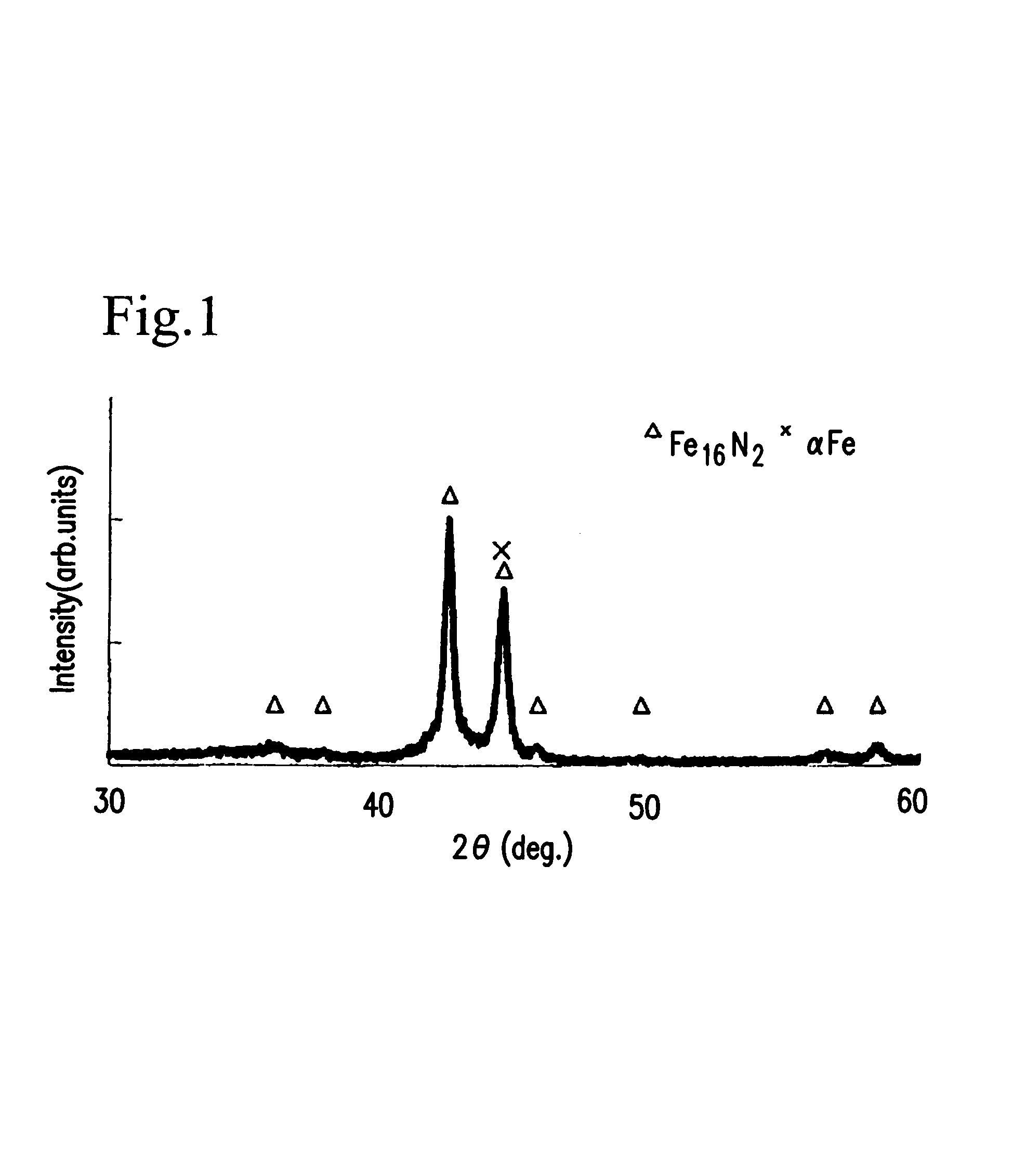
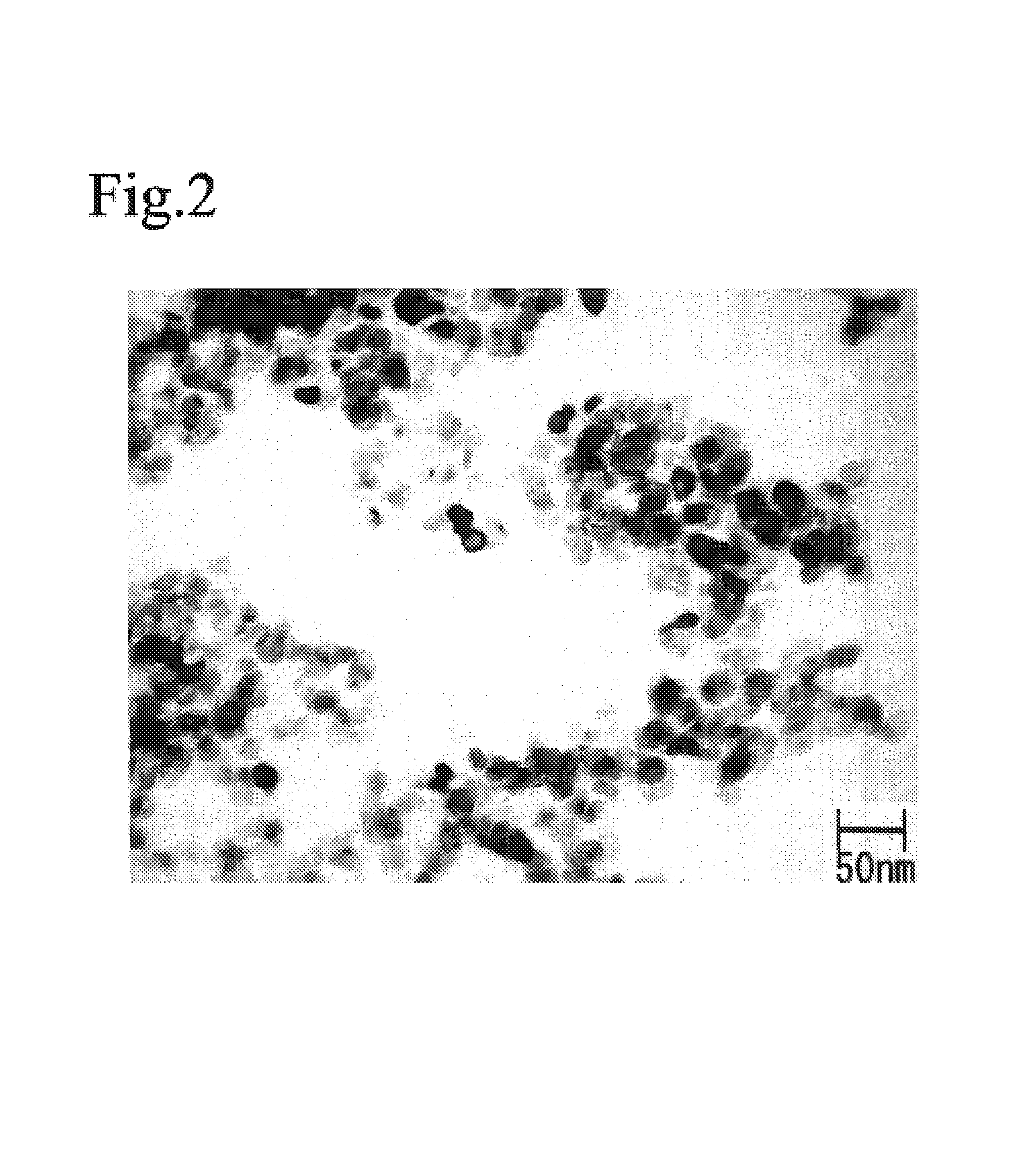
[0012]To achieve the above object, the present inventors have made extensive researches. As a result, it has been found that an iron nitride magnetic powder, which comprises at least a Fe16N2 phase and has an substantially spherical or ellipsoidal particle shape and a very small particle size such as an average particle size of 5 to 30 nm, has an extremely high coercive force and a saturation magnetization suitable for high density recording, and that, when such a magnetic powder is used, a very thin magnetic layer suffering from no or little decrease of output due to recording demagnetization can be realized, a high output is achieved, and excellent short wavelength recording properties are achieved.
[0013]In the present invention, an axis ratio (a ratio of a major axis to a minor axis) of the substantially spherical or ellipsoidal particles is preferably 2 or less, more preferably from 1 to 1.5, as shown in FIG. 2. When the axis ratio exceeds 2, a part of the magnetic powder particles may stand in a direction across the surface of a magnetic layer in the course of coating a magnetic paint, so that the surface smoothness of the magnetic layer deteriorates and thus electromagnetic conversion properties are worsened.
[0015]It has also been found that, when the iron nitride magnetic powder contains at least one element selected from the group consisting of rare earth elements, silicon and aluminum, the maintenance of the shape of the magnetic particles in a heat-treatment step and the dispersibility of the particles in a magnetic paint are improved, the magnetic layer is further made thin, and also the excellent short wavelength recording properties, which are hardly achieved by the prior art, can be attained.

Problems solved by technology

When the axis ratio exceeds 2, a part of the magnetic powder particles may stand in a direction across the surface of a magnetic layer in the course of coating a magnetic paint, so that the surface smoothness of the magnetic layer deteriorates and thus electromagnetic conversion properties are worsened.

Method used


Image

  • Magnetic recording medium containing particles with a core containing a Fe16N2 phase
  • Magnetic recording medium containing particles with a core containing a Fe16N2 phase

Examples


example 1

(A) Preparation of Iron Nitride Magnetic Powder

[0131]Magnetite particles having a substantially spherical shape and an average particle size of 25 nm (10 g) was dispersed in water (500 cc) with an ultrasonic disperser for 30 minutes. To this dispersion, yttriumnitrate (2.5 g) was added and dissolved followed by stirring for 30 minutes.

[0132]Separately, sodium hydroxide (0.8 g) was dissolved in water (100 cc). This aqueous solution of sodium hydroxide was dropwise added to the above dispersion over about 30 minutes. After the addition of the aqueous solution, the mixture was stirred for further 1 hour. Thereby, yttrium hydroxide was deposited on the surfaces of the magnetite particles. Then, the magnetite particles was washed with water and filtrated. The recovered particles were dried at 90° C. to obtain a powder comprising the magnetite particles the surfaces of which were covered with yttrium hydroxide.

[0133]The powder comprising the magnetite particles the surfaces of which were ...

example 2

[0146]A magnetic tape was produced in the same manner as in Example 1 except that the thickness of the magnetic layer after the orientation in a magnetic field, drying and calendering was changed to 50 nm in the production process of the magnetic tape, and then the tape was set in a cartridge to obtain a tape for a computer.

example 3

[0147]In the production process of an iron nitride magnetic powder according to Example 1, the magnetic powder, which had been coated with yttrium hydroxide, was redispersed in a solution of 0.07 mole of boric acid dissolved in 30 cc of water, then the dispersion was filtrated and the powder was dried at 60° C. for 4 hours to remove water. Thereby, a magnetic powder, the particles of which were covered with yttrium containing boron, was obtained. This magnetic powder was reduced with hydrogen, nitrided with ammonia and stabilized in the same manner as in Example 1 to obtain a yttrium-iron nitride-boron magnetic powder.

[0148]The contents of yttrium and nitrogen of the resulting yttrium-iron nitride-boron magnetic powder were analyzed with a fluorescent X-ray analysis and 4.0 atomic % and 9.0 atomic %, respectively, based on the amount of iron. The content of boron was 3.0 atomic %. The X-ray diffraction pattern showed the profile corresponding to the Fe16N2 phase.

[0149]Furthermore, t...


PUM


Abstract

A magnetic recording medium comprising a nonmagnetic support and a magnetic layer formed on the support and containing a magnetic powder and a binder, wherein said magnetic powder comprises substantially spherical or ellipsoidal particles and at least one element selected from the group consisting of rare earth elements, silicon and aluminum, and has a Fe16N2 phase, an average particle size of 5 to 30 nm and an axis ratio (a ratio of a major axis to a minor axis) of 1 to 2. This magnetic recording medium achieves a high output and has excellent short wavelength recording properties, since it uses a magnetic powder having a very small particle size and has a very high coercive force and a saturation magnetization suitable for high density recording.

Description

FIELD OF THE INVENTION[0001]The present invention relates to a magnetic recording medium comprising magnetic powder particles having substantially spherical or ellipsoidal shapes which comprise at least iron and nitrogen as constituent elements. In particular, the present invention relates to a magnetic recording medium suitable for high density recording such as a digital video tape, a backup tape for a computer, etc.BACKGROUND ART[0002]Coating type magnetic recording media, that is, magnetic recording media comprising a nonmagnetic support and a magnetic layer formed on the support and comprising magnetic powder and a binder, are required to have a further increased recording density with the shift of a writing-reading system from an analog system to a digital one. In particular, such requirement has been increased year by year in the video tapes and the backup tapes for computers which are used for high density recording.[0003]To cope with short wavelength recording which is inev...

Claims


Application Information

Patent Timeline
IPC IPC(8): G11B5/706G11B5/712G11B5/70G11B5/714H01F10/12H01F10/14
CPCG11B5/70615G11B5/714H01F10/126H01F10/142G11B5/70G11B5/70605G11B5/712G11B5/73H01F1/06
Inventor SASAKI, YUJIKISHIMOTO, MIKIOUSUKI, NAOKI
Owner FUJIFILM CORP
Learn More