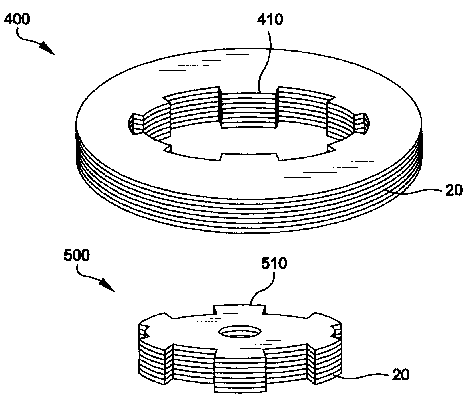
Although amorphous metals offer superior magnetic performance when compared to non-oriented electrical steels, they have long been considered unsuitable for use in bulk
magnetic components such as the rotors and stators of electric motors due to certain physical properties and the ensuing impediments to fabrication.
For example, amorphous metals are thinner and harder than non-oriented steel, and consequently cause fabrication tools and dies to wear more rapidly.
The resulting increase in the tooling and manufacturing costs makes fabricating bulk amorphous metal
magnetic components using such conventional techniques, such as
punching and
stamping, commercially impractical.
The thinness of amorphous metals also translates into an increased number of laminations in the assembled components, further increasing the total cost of an amorphous metal rotor or
stator magnet assembly.
However, amorphous metal is a very hard material, making it very difficult to
cut or form easily.
Once annealed to achieve peak magnetic properties, amorphous metal ribbon becomes very brittle.
This makes it difficult and expensive to use conventional approaches to construct a bulk amorphous metal magnetic component.
The
brittleness of amorphous metal ribbon may also cause concern for the durability of the bulk magnetic component in an application such as an
electric motor.
These magnetic forces are capable of placing considerable stresses on the
stator material, and may damage an amorphous metal magnetic
stator.
A limited number of non-conventional approaches have been proposed for constructing amorphous metal components.
Although this method permits formation of complex stator shapes, the structure contains numerous air gaps between the discrete flake particles of amorphous metal.
A non-magnetic material is inserted into the joints between the wound pieces and pole pieces, increasing the effective gap, and thus increasing the reluctance of the
magnetic circuit and the
electric current required to operate the motor.
This configuration further increases the reluctance of the stator, because contiguous
layers of the wound pieces and of the pole pieces meet only at points, not along full line segments, at the joints between their respective faces.
Even small sections of recrystallized amorphous metal will normally increase the magnetic losses in the stator to an unacceptable level.
Another difficulty associated with the use of ferromagnetic amorphous metals arises from the phenomenon of
magnetostriction.
As an amorphous metal magnetic stator is stressed, the efficiency at which it directs or focuses
magnetic flux is reduced, resulting in higher magnetic losses, reduced efficiency, increased heat production, and reduced power.
As a result, stress levels that would not have a deleterious effect on the magnetic properties of these conventional metals have a severe
impact on magnetic properties important for motor components, e.g. permeability and core loss.
For example, the '649 patent further discloses that forming amorphous metal cores by rolling amorphous metal into a coil, with lamination using an
epoxy, detrimentally restricts the thermal and magnetic saturation expansion of the coil of material, resulting in high internal stresses and
magnetostriction that reduces the efficiency of a motor or generator incorporating such a core.
The limitations of
magnetic components made using existing materials entail substantial and undesirable design compromises.
In many applications, the core losses of the electrical steels typically used in motor components are prohibitive.
Furthermore, the desirable soft magnetic properties of the permalloys are adversely and irreversibly affected by plastic deformation, which can occur at relatively
low stress levels.
However, the increase in frequency also markedly increases the magnetic losses of these components.
The limitations of magnetic components made using existing materials entail substantial and undesirable design compromises.
In many applications, the core losses of the common electrical steels are prohibitive.
Furthermore, the desirable soft magnetic properties of the permalloys are adversely and irreversibly affected by plastic deformation which can occur at relatively
low stress levels.
While soft ferrites often have attractively low losses, their low induction values result in impractically large devices for many applications wherein space is an important consideration.
Moreover, the increased size of the core undesirably necessitates a longer electrical winding, so ohmic losses increase.
However, the gapped toroidal geometry affords only minimal design flexibility.
It is generally difficult or impossible for a device user to adjust the gap so as to select a desired degree of shearing and
energy storage.
In addition, the equipment needed to apply windings to a toroidal core is more complicated, expensive, and difficult to operate than comparable winding equipment for laminated cores.
Oftentimes a core of toroidal geometry cannot be used in a
high current application, because the heavy gage wire dictated by the rated current cannot be bent to the extent needed in the winding of a toroid.
As a result, they are not well suited and are difficult to adapt for polyphase transformers and inductors, including especially common three-phase devices.
Moreover, the stresses inherent in a strip-wound toroidal core give rise to certain problems.
In addition, gapping a wound toroid frequently causes additional problems.
Therefore the actual gap tends to close or open in the respective cases by an unpredictable amount as required to establish a new
stress equilibrium.
Therefore, the final gap is generally different from the intended gap, absent corrective measures.
Since the
magnetic reluctance of the core is determined largely by the gap, the magnetic properties of finished cores are often difficult to reproduce on a consistent basis in the course of high-volume production.
Such a process understandably entails significant manual labor and manipulation steps involving brittle annealed amorphous metal ribbons.
These steps are especially tedious and difficult to accomplish with cores smaller than 10 kVA.
Furthermore, in this configuration, the cores are not readily susceptible to controllable introduction of an air gap, which is needed for many
inductor applications.


