pipe cleaning device

A technology for cleaning devices and pipes, used in water supply devices, waterway systems, transportation and packaging, etc., can solve problems such as high stress and failure, multiple winding times, large tension, etc., to achieve compact structure, avoid shortcomings, and excellent economy. Effect

Active Publication Date: 2020-02-14
卡尔·维德曼
View PDF14 Cites 0 Cited by
  • Summary
  • Abstract
  • Description
  • Claims
  • Application Information

AI Technical Summary

Problems solved by technology

As a result, strong deflections are created when winding the suction hose from the storage winch onto the steering winch, which can lead to high stresses and failures
In addition, in the case of an arrangement with only one steering winch, in order to achieve a relatively high pulling force, a relatively high number of windings is required, so that the same problems can occur on the steering winch as in the storage winch according to DE 38 13 419 A1. question

Method used


Image

  • pipe cleaning device
  • pipe cleaning device
  • pipe cleaning device

Examples


Embodiment Construction

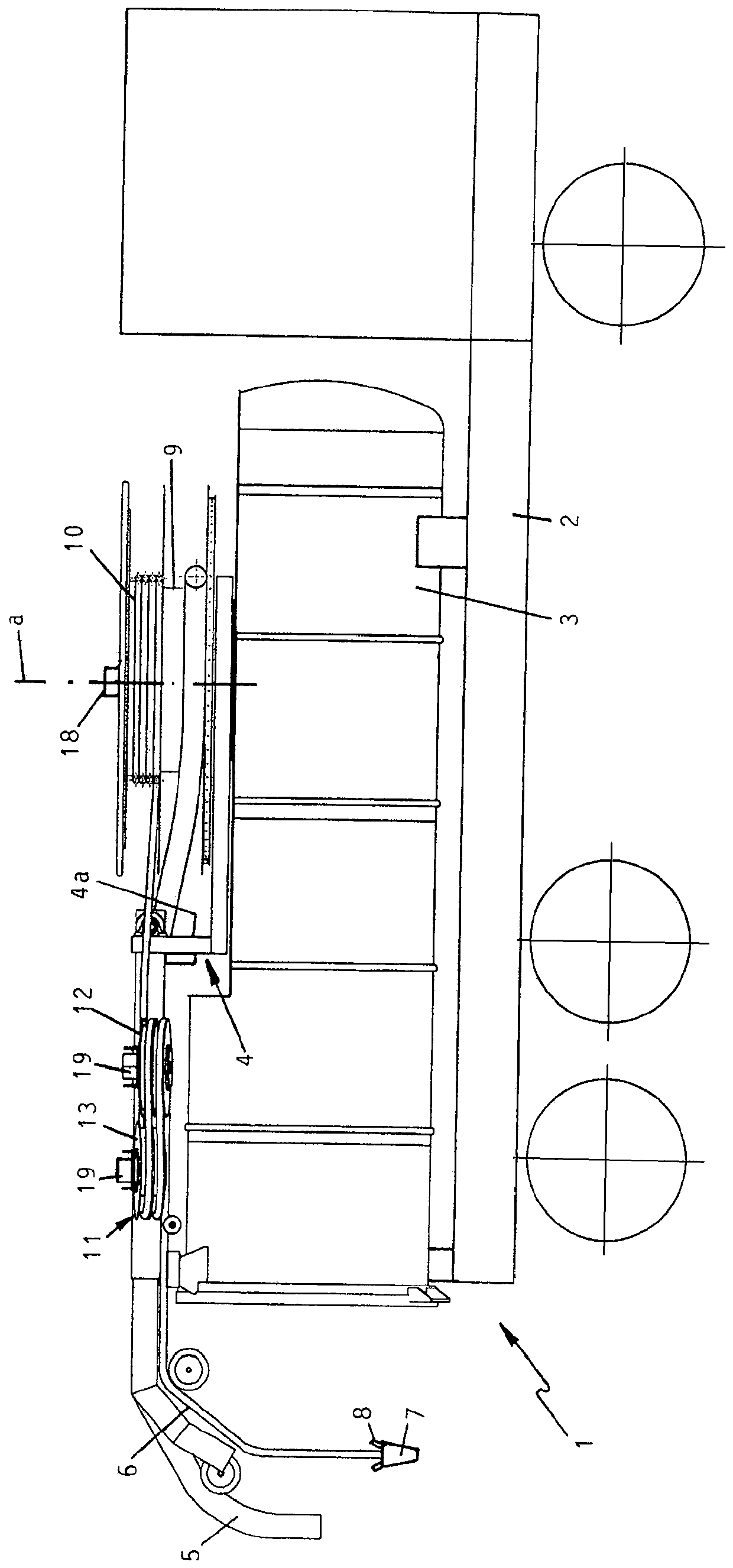
[0017] The main field of application of the invention is vehicles with a design designed as a pipe cleaning device, so-called pipe cleaning vehicles, the basic design and mode of operation of which are known.

[0018] exist figure 1 The pipe cleaning vehicle 1 shown in contains a container 3, preferably in the form of a bucket, which is accommodated on the chassis 2 and has, not shown in detail, for the water required for cleaning the pipes and the water generated during the cleaning of the pipes. Cavity for mud sucked from the pipe. On this container 3 is accommodated a cantilever 4 which can be swiveled about a vertical axis a, a suction hose 5 which can be sunk into the pipeline, can be subjected to suction by means of a vacuum source not shown in detail, and can be introduced into the pipeline. The flushing hose 6, which can be loaded with high-pressure water, is unwound through the boom. For this purpose, the cantilever 4 can point downwards at the rear end in the form ...


PUM


Abstract

A sewer cleaning device has a rinsing hose, to which pressurized water is applied, which is stored on an assigned storage reel and which passes through a transportation apparatus adjacent to the storage reel. A manner of operating, which protects the rinsing hose, is achieved by providing a reel arrangement, around which the rinsing hose is wrapped at least once, having two redirection reels arranged laterally adjacent to one another in the radial direction, which are offset in relation to one another in the axial direction by at least the thickness of the rinsing hose and of which at least one redirection reel is arranged tilted about an axis of symmetry, which perpendicularly intersects the axes of the two redirection reels, so that during each complete wrap around the reel arrangement forming the transportation apparatus by the rinsing hose, a pitch of the path assigned to the rinsing hose results.

Description

technical field [0001] The invention relates to a pipe cleaning device with a flushing hose loaded with high-pressure water, which can be stored on an associated storage winch and passed through a conveying device adjacent to this storage winch, the conveying device having a Flush the winch mechanism with the hose wrapped at least one turn. Background technique [0002] DE 38 13 419 A1 shows a pipe cleaning device with a conveying device adjacent to a storage winch. This conveying device consists of two conveying rollers which can be pressed against one another, between which the flushing hose is guided. However, only relatively low pulling forces can be transmitted to the flushing hose with this type of conveying device. Accordingly, known conveying devices are only used to pull the rinsing hose off the storage drum. The known conveying devices are not suitable for pulling the flushing hose back out of the pipeline. That is to say that a high tensile force is required t...

Claims


Application Information

Patent Timeline
Patent Type & Authority Patents(China)
IPC IPC(8): B65H75/42B65H51/12B65H75/14
CPCB65H51/12B65H75/14B65H75/425B65H2701/33E03F7/106B60P3/225B60P3/2265B65H57/14B65H75/265
Inventor 卡尔·维德曼
Owner 卡尔·维德曼
Why Eureka
Try Eureka