Bonding structure for a hard disk drive suspension using anisotropic conductive film

a technology of anisotropic conductive film and hard disk drive, which is applied in the direction of supporting heads, printed electric components, and maintaining head carrier alignment, etc., can solve the problems of increasing the cost of ultrasonic bonding and soldering, the difficulty of one-time bonding, and the inability to separate the bonded parts in the future to be reworked without damaging the fpc or the suspension. , to achieve the effect of reducing the size of the bonding

Inactive Publication Date: 2007-04-17
SAE MAGNETICS (HK) LTD
View PDF5 Cites 21 Cited by
  • Summary
  • Abstract
  • Description
  • Claims
  • Application Information

AI Technical Summary

Benefits of technology

[0008]It is an object of the present invention to overcome the complexities of prior art approaches of ultrasonic bonding and soldering. This invention will alleviate the difficulty of one-time bonding in the case of ultrasonic bonding, and avoid high-temperature bonding required in soldering.
[0009]It is another objective of the present invention to reduce the bonding pad size and floating capacity.
[0010]Yet another objective of the present invention is to reduce the space between bonding pads ...

Problems solved by technology

However, the pressing of the flying leads of the FPC entails complex processing, and ultrasonic bonding to different bonding pads is very difficult to contact Moreover, bonded parts cannot be separated in the future to be reworked without damaging the FPC or the suspension.
However, this process requires for...

Method used


Image

  • Bonding structure for a hard disk drive suspension using anisotropic conductive film
  • Bonding structure for a hard disk drive suspension using anisotropic conductive film
  • Bonding structure for a hard disk drive suspension using anisotropic conductive film

Examples


Embodiment Construction

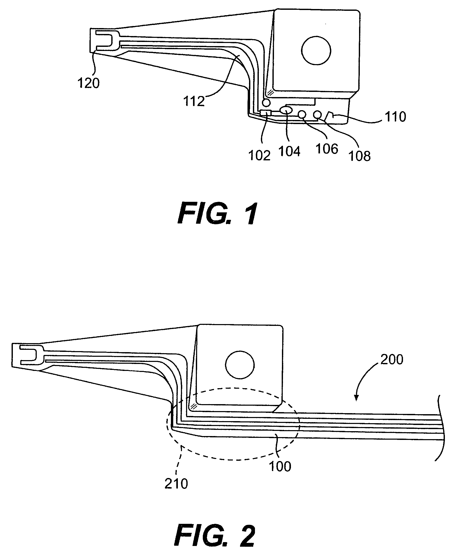
[0028]Referring to FIG. 1, this is a standard wireless suspension. Trace 112 is patterned on top of a flexture piece which runs from slider 120 to bonding pads 102, 104, 106, and 108, transporting electromagnetic signals from slider 120. Base plate 100 supports bonding pads 102, 104, 106, 108, to which a FPC is bonded for transmitting signals to elsewhere in a hard disk drive, such as a circuit on the actuator arm. The number of contact pads shown here is for illustrative purposes only, and there could be more or fewer contact pads without deviating from the spirit of the invention.

[0029]Referring to FIG. 2, a FPC 200 is attached to contact pads 102, 104, 106, 108 (not shown) in the circled area 210. Traditionally, FPC can be bound to contact pads using ultrasonic bonding or soldering. With soldering, additional solder bumps need to be incorporated. As mentioned, both prior art bonding methods tend to be cost- and labor-intensive, and bonding using anisotropic conductive adhesive, s...


PUM


Abstract

A plurality of bonding structures and their forming methods for bonding a FPC to a bonding pad, in particular a bonding pad of a wireless suspension in a head gimbal assembly, using anisotropic conductive adhesive; such structures eliminate the spring-back force in typical anistropic bonding to ensure durable bonding. At the same time, these structures also allow for reworkability under which the bonded parts can be separated easily.

Description

[0001]This application is a continuation of U.S. patent application Ser. No. 09 / 696,276, filed Oct. 25, 2000, now U.S. Pat. No. 6,703,566.BACKGROUND OF THE INVENTION[0002]This invention generally relates to the field of disk drives, and more particularly to forming optimal structures for bonding in a head gimbal assembly using anisotropic conductive adhesive.[0003]With the rapid progress of miniaturizing and thinning technology for electronic devices, high-density inner wiring systems including flex-print circuit (FPC) have become essential. At the same time, micro-connecting technology for the connection of FPC with other electronic parts, such as the traces on a magnetic head suspension assembly, is indispensable.[0004]Traditionally the FPC is capable of adopting ultrasonic bonding. The connecting terminals of the FPC are plated with gold; the flying leads of the FPC are aligned with and pressed to the bonding pad on the suspension with sufficient force to keep the alignment and a...

Claims


Application Information

Patent Timeline
IPC IPC(8): H05K1/16G11B5/60G11B21/02G11B21/21H05K1/14H05K3/32H05K3/36
CPCH05K3/361H05K1/056H05K3/243H05K3/323H05K3/4007H05K3/4015H05K2201/0367H05K2201/10234G11B5/4846
Inventor SHIRAISHI, MASASHIYAGI, ICHIRO
Owner SAE MAGNETICS (HK) LTD
Why Eureka
Try Eureka