
Oxygen and nitrogen enriched atmospheres in aircraft

a technology of airspace and oxygen, applied in the direction of nitrogen purification/separation, membranes, separation processes, etc., can solve the problems of increasing the cost of an aircraft, and increasing the cost of a fuselage, so as to improve the breathable atmosphere

Inactive Publication Date: 2007-02-20
SMARTMEMBRANE CORP
View PDF40 Cites 29 Cited by
  • Summary
  • Abstract
  • Description
  • Claims
  • Application Information

AI Technical Summary

Benefits of technology

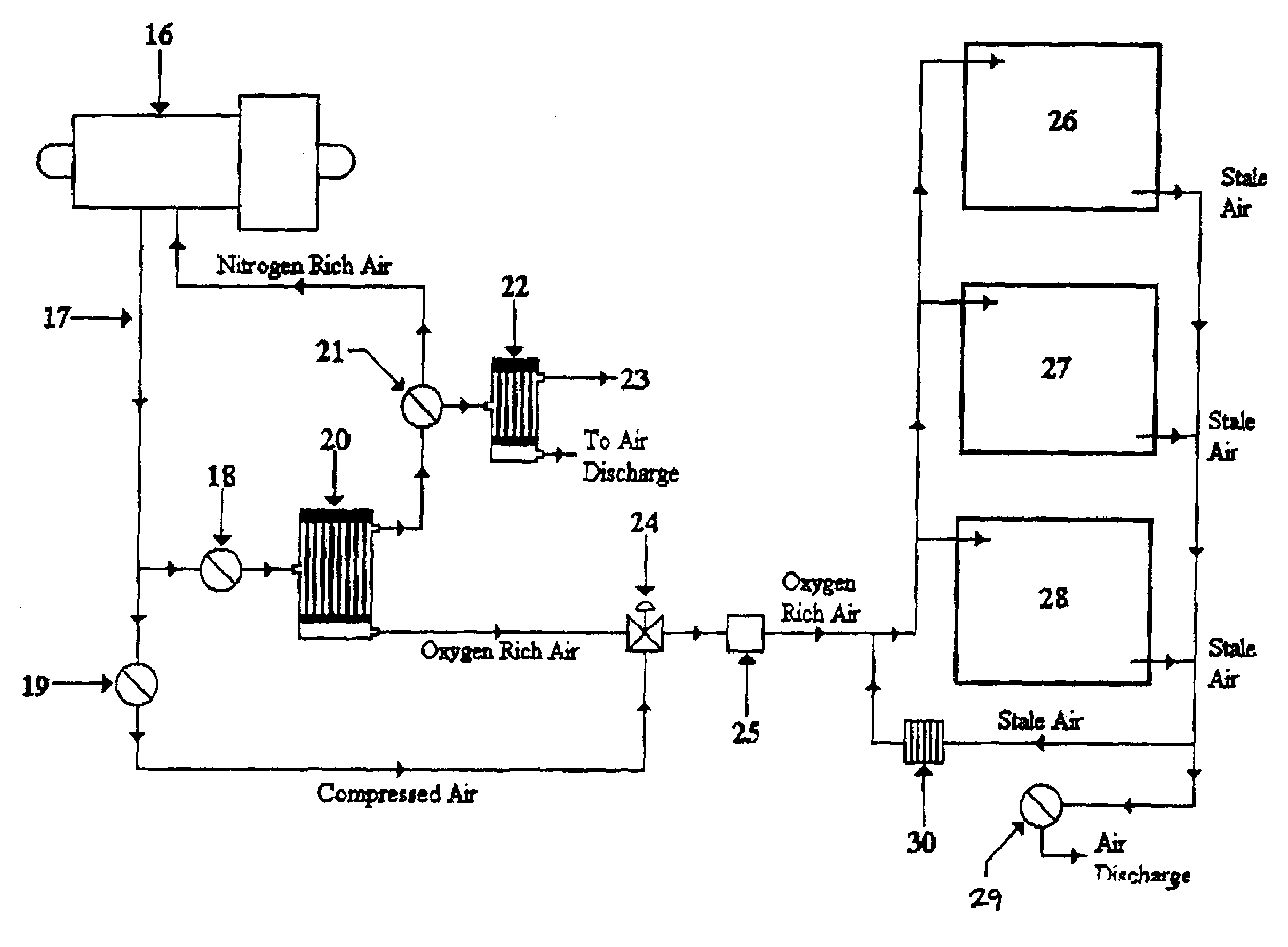
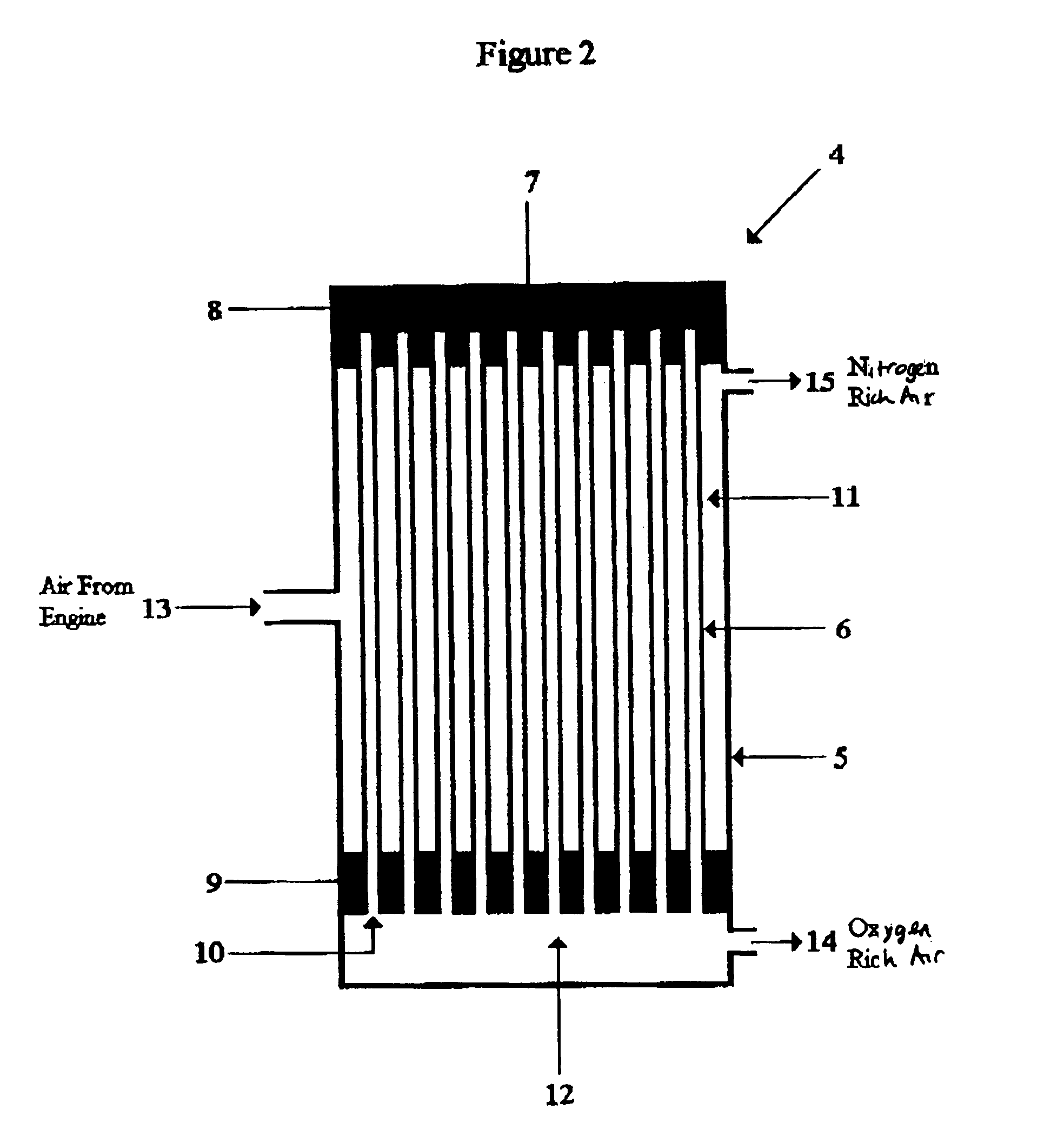
"The present invention provides a composite hollow fibre gas separation system that can produce large volumes of enriched oxygen air for use on board aircraft. The system has high gas permeability and reasonable gas selectivity, making it efficient in energy usage and lightweight. The gas separation unit can be manufactured from a relatively lightweight material, making it suitable for use on board aircraft. The gas separation system can provide enough enriched oxygen air to meet the air supply requirements of a typical large passenger aircraft. The enriched oxygen air is beneficial for the health of passengers and can help prevent pulmonary embolism. The gas separation system is also able to produce sufficient nitrogen-enriched air for an inert atmosphere inside the aircraft."

Problems solved by technology

As altitude increases, the atmospheric pressure falls and humans become much more vulnerable to the effects of hypoxia.
Strengthening the fuselage increases the cost of an aircraft, and the increased weight of the fuselage also has a significant impact on the fuel consumption and potential range of the aircraft.
However, the partial pressure of the oxygen inside an aircraft pressurised to 76.7 kPa is about 25% less than the corresponding pressure at sea level, and prolonged exposure to this lower partial pressure could still have an adverse affect on the health of passengers.
For example, passengers particularly at risk of hypoxia include those with pulmonary and heart diseases who find breathing difficult and have impaired oxygen uptake even under normal atmospheric conditions.
Their breathing difficulties would be exacerbated under reduced oxygen partial pressure conditions, and hypoxia in such vulnerable passengers could well precipitate heart attacks and strokes during flight.
There is also an increased risk of clots forming in the deep veins of legs, particularly during long-haul flights because of the combination of hypoxia and long periods of immobility inside aircraft cabins, and such deep vein clots could lead to pulmonary embolism after landing.
Worryingly, cases have also been reported where fit, younger, passengers have apparently suffered from hypoxia related illnesses either during or after long-haul flights.
Carbon dioxide is an asphyxiant, and as little as a 2% concentration of carbon dioxide in the atmosphere can initiate headaches, increase blood pressure and cause deeper respiration.
However, there are cost implications in taking compressed air from the engines for use other than for motive power.
Until recently, however, very little attention has been given to the concentration of oxygen in the breathable atmosphere supplied to passengers inside aircraft.
However, modern passenger aircraft carry large numbers of passengers, and it is not practical to use pure oxygen to increase the oxygen concentration in the breathable atmosphere inside the aircraft.
For example, packaged oxygen, i.e. oxygen in the form of either compressed gas in cylinders or liquid in tanks, would not only be extremely expensive, but would also have serious weight implications for the aircraft.
However, industrial oxygen production systems are very large, heavy and energy intensive, and such systems are not a practical solution for passenger aircraft applications.
However, very high volumes of air are required to conform with the passenger air supply regulations specified by the air transport authorities, and the industrial oxygen concentrators available at the time of the above patent application were unable to efficiently supply such large amounts of enriched oxygen air.
The need to use high pressure to produce the oxygen rich air imposes high energy demands on the gas separation system, and their low gas flux also limits the volume of oxygen rich air that can be produced from such concentrators.
It is therefore impractical to use industrial oxygen concentrators to produce the large amounts of oxygen rich air needed to meet the requirements of a typical passenger aircraft air conditioning system.

Method used


Image

  • Oxygen and nitrogen enriched atmospheres in aircraft
  • Oxygen and nitrogen enriched atmospheres in aircraft
  • Oxygen and nitrogen enriched atmospheres in aircraft

Examples


Embodiment Construction

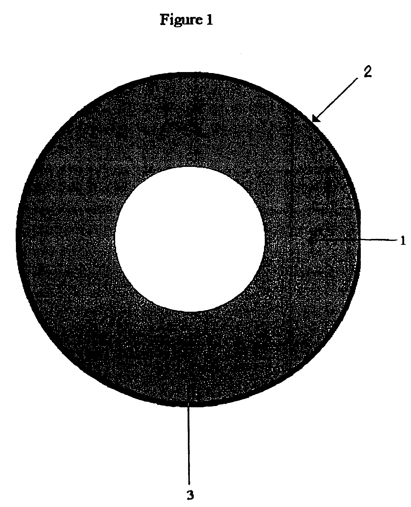
[0061]The basic construction of the composite hollow fibre membrane is illustrated in FIG. 1. A very porous hollow fibre tube 1, manufactured from polyethersulfone polymer, supports a very thin layer 2 of selective polymer coated onto the outer surface 3 of the fibre tube 1. The selective polymer consists of a mixture of non cross-linked polydimethylsiloxane and cross-linked polydimethylsiloxane

[0062]Both polyethersulfone and polydimethylsiloxane are widely used to manufacture hollow fibre membranes and their physical and chemical resistance properties are well known and well understood.

[0063]The hollow fibre tube is manufactured by extruding polyethersulfone polymer solution through a triple spinneret, and the extrusion conditions are controlled so as to provide a very porous fibre tube structure.

[0064]A particular feature of the hollow fibre tube used in the aircraft gas separation system is that, after extrusion, the polyethersulfone fibre is subjected to a special modification t...


PUM

PropertyMeasurementUnit
pressureaaaaaaaaaa
pressureaaaaaaaaaa
pressureaaaaaaaaaa

Abstract

A method of supplying oxygen rich air to the passengers and crew on board a passenger aircraft by use of a highly permeable oxygen enrichment unit, wherein the fiber tubes of the hollow fiber membranes used to separate normal air into oxygen rich and nitrogen rich fractions in the oxygen enrichment unit are subjected to a modification technique before the tubes are coated with a selective polymer.

Description

FIELD OF THE INVENTION[0001]The present invention relates to a composite hollow fibre membrane gas separation system, where the hollow fibre membranes are capable of being modified so that the gas separation system can produce either large volumes of slightly enriched separated gas streams or small volumes of highly enriched separated gas streams.[0002]The gas separation system is able to operate under relatively low differential pressure conditions and the gas separation module that contains the hollow fibre membranes can therefore be made from lightweight materials.[0003]This combination of low pressure operation and light weight makes the gas separation system particularly suitable for passenger aircraft applications. For example, one form of the gas separation system could be used to supply oxygen rich air to passengers in an aircraft, whilst another form of the gas separation system could be used to supply inert nitrogen rich air to the fuel tanks of the aircraft.DISCUSSION OF ...

Claims


Application Information

Patent Timeline
Patent Type & Authority Patents(United States)
IPC IPC(8): B01D53/22B01D67/00B01D69/02B01D69/08B01D69/10B01D71/68B01D71/70C01B13/02C01B21/04C08L81/06
CPCB01D53/22C08L81/06B01D63/02B01D67/0088B01D69/02B01D69/08B01D69/10B01D71/68B01D71/70C01B13/0255C01B21/0444B01D53/228B01D2313/38C01B2210/0045C01B2210/0046B01D2313/221B01D69/107B01D71/701B01D63/021C08G75/23C08J7/04
Inventor LYONS, ARTHURVAN DEN GROSS, ANDREW
Owner SMARTMEMBRANE CORP
Learn More