
Sulfonate and resist composition

Inactive Publication Date: 2005-10-04
SUMITOMO CHEM CO LTD
View PDF3 Cites 0 Cited by
  • Summary
  • Abstract
  • Description
  • Claims
  • Application Information

AI Technical Summary

Benefits of technology

[0008]An object of the present invention is to provide a novel sulfonate and to provide a chemical amplification type resist composition comprising the above-mentioned sulfonate and a resin component, and suitable for excimer laser lithography using ArF, KrF and the like, showing excellent various resist abilities such as sensitivity, resolution and the like, and giving particularly improved line edge roughness and pattern profiles.

Problems solved by technology

However, in conventionally known chemical amplification type resist compositions, there is a problem that line edge roughness occurs by generation of standing wave and the like, namely, smoothness on a pattern side wall decreases, and resultantly, uniformity of line width deteriorates.
Though it is known that the use of an acid generator including anion of benzenesulfonic acid having at least one ester group in a positive type photosensitive composition, it is still difficult to combine progress of roughness and progress of pattern shapes.

Method used


Image

  • Sulfonate and resist composition
  • Sulfonate and resist composition
  • Sulfonate and resist composition

Examples


synthesis example 1

RESIN SYNTHESIS EXAMPLE 1

Synthesis of Resin A1

[0121]2-Ethyl-2-adamantyl methacrylate, 5-methacryloyloxy-2,6-norbornenelactone and α-methacryloyloxy-γ-butyrolactone were charged at a molar ratio of 35:40:25 (12.42 g:12.70 g:5.58 g), and 30.70 g of 1,4-dioxane was added, and then was added 0.70 g of azobisisobutyronitrile as an initiator to prepare solution. In another flask, 46.04 g of 1,4-dioxane was charged and heated to 87° C. To this was added the solution obtained above over one hour and the mixture was stirred for 5 hours maintaining the temperature. Then, operation of pouring into large amount of n-heptane to cause crystallization was repeated three times for purification, and then dried to obtain 25.4 g (Yield: 82.7%) of copolymer having an average molecular weight of 8900. This is called resin A1.

synthesis example 2

RESIN SYNTHESIS EXAMPLE 2

Synthesis of Resin A2

[0122]2-Ethyl-2-adamantyl methacrylate, 3-hydroxy-1-adamantyl methacrylate and α-methacryloyloxy-γ-butyrolactone were charged at a molar ratio of 5:2.5:2.5 (20.0 parts:9.5 parts:7.3 parts), and methyl isobutyl ketone in twice weight based on all monomers was added, to prepare solution. To the solution was added azobisisobutyronitrile as an initiator in a ratio of 2 mol % based on all monomer molar amount, and the mixture was heated at 80° C. for about 8 hours. Then, the reaction solution was poured into large amount of heptane to cause precipitation, and this operation was repeated three times for purification. As a result, copolymer having a weight-average molecular weight of about 9,200 was obtained. This is called resin A2.

[0123]As Resin A3, IHM-55-10K (Trade No., the product of Mitsubishi Rayon Co., Ltd., mixture of structural units of MAMA and HGBME each of which structure is shown below, ratio of MAMA / HGBMA=1 / 1) was used.

[0124]Res...


PUM

PropertyMeasurementUnit
Percent by moleaaaaaaaaaa
Temperatureaaaaaaaaaa

Abstract

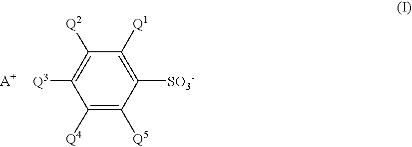
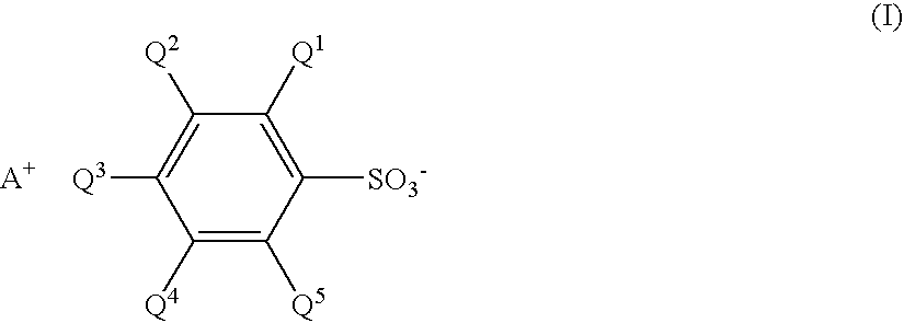
The present invention provides a sulfonate of the formula (I): wherein Q1, Q2, Q3, Q4 and Q5 each independently represent hydrogen, alkyl having 1 to 16 carbon atoms, alkoxy having 1 to 16 carbon atoms, halogen, aryl having 6 to 12 carbon atoms, aralkyl having 7 to 12 carbon atoms, cyano, sulfide, hydroxy, nitro or a group of the formula (I′)—COO—X—Cy1  (I′)wherein X represents alkylene and at least one —CH2— in the alkylene may be substituted by —O— or —S—, and Cy1 represents alicyclic hydrocarbon having 3 to 20 carbon atoms,and A+ represents a counter ion, with the proviso that at least one of Q1, Q2, Q3, Q4 and Q5 is the group of the formula (I′).The present invention also provides a chemical amplification type positive resist composition comprising a sulfonate of the formula (I) and resin which contains a structural unit having an acid labile group and which itself is insoluble or poorly soluble in an alkali aqueous solution but becomes soluble in an alkali aqueous solution by the action of an acid.

Description

BACKGROUND OF THE INVENTION[0001]1. Field of the Invention[0002]The present invention relates to a novel sulfonate and resist composition using the sameused in fine processing of semiconductors.[0003]2. Prior Art[0004]Semiconductor microfabrication employs a lithography process using a resist composition. In lithography, theoretically, the shorter the exposure wavelength becomes, the higher the resolution can be made, as expressed by Rayleigh's diffraction limit formula. The wavelength of an exposure light source for lithography used in the manufacture of semiconductor devices has been shortened year by year as g line having a wavelength of 436 nm, i line having a wavelength of 365 nm, KrF excimer laser having a wavelength of 248 nm and ArF excimer laser having a wavelength of 193 nm. F2 excimer laser having a wavelength of 157 nm seems to be promising as the next-generation exposure light source. Further, as the exposure light source of the subsequent generation, soft X ray (EUV) h...

Claims


Application Information

Patent Timeline
IPC IPC(8): C07C309/58C07C309/00C07C381/00C07C381/12G03F7/039G03F7/004
CPCC07C309/58C07C381/12G03F7/0045G03F7/0392G03F7/0397C07C2101/14C07C2102/42Y10S430/111Y10S430/106C07C2103/74C07C2601/14C07C2602/42C07C2603/74
Inventor YAMAGUCHI, SATOSHIUETANI, YASUNORIMORIUMA, HIROSHI
Owner SUMITOMO CHEM CO LTD
Learn More