
Magnetic recording disk

a magnetic recording and magnetic technology, applied in the field of magnetic recording mediums, can solve the problems of poor accuracy, large variation of surface irregularities, and attract the head, and achieve the effects of less chemical reaction, less sublimation, and increased temperature of the disk surface and reaction produ

Inactive Publication Date: 2001-02-27
EBARA CORP
View PDF5 Cites 14 Cited by
  • Summary
  • Abstract
  • Description
  • Claims
  • Application Information

AI Technical Summary

Benefits of technology

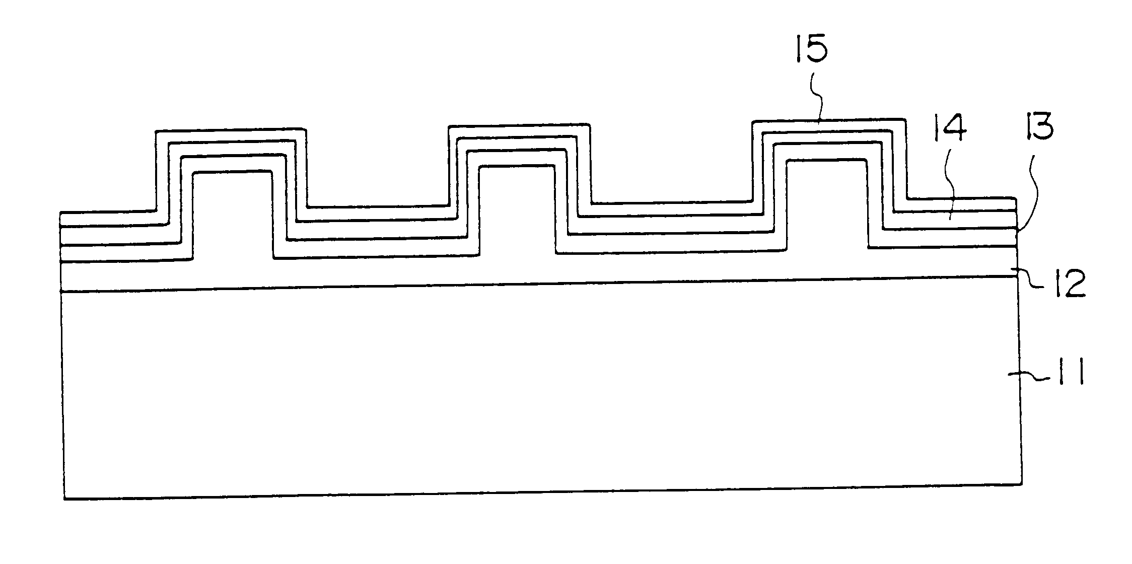
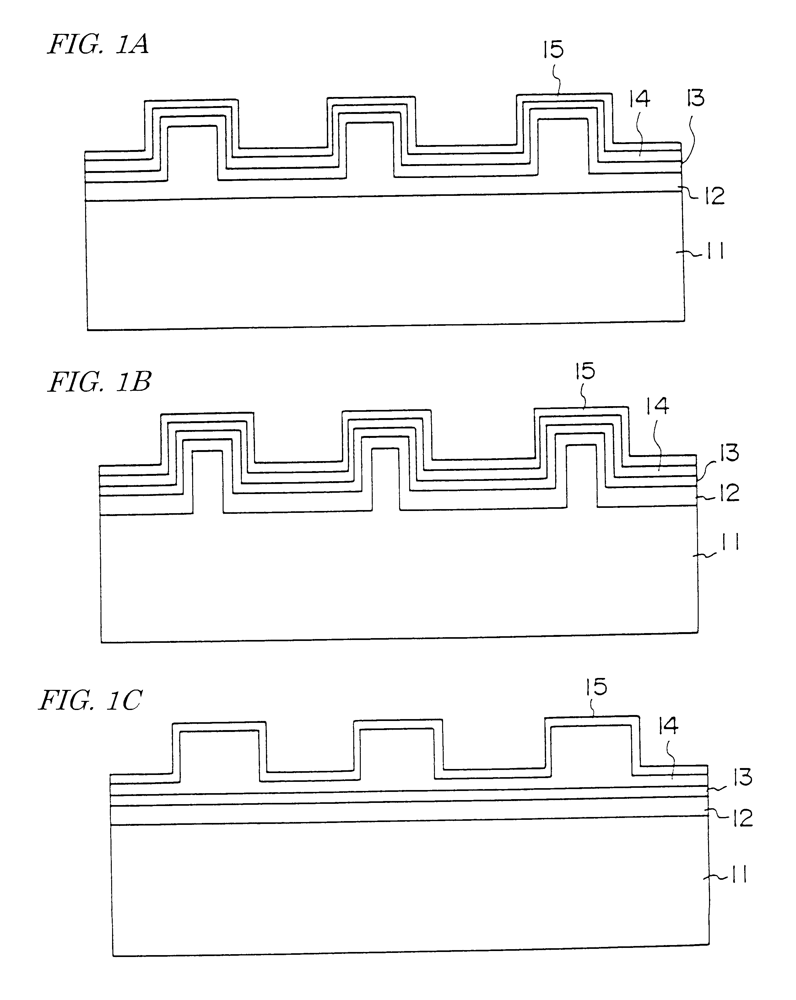
According to the present invention, there is provided a magnetic recording disk having a substrate coated on a surface thereof with a magnetic layer, a carbon layer, and a lubricating film. The substrate has on a surface thereof a texture structure of fine surface irregularities for reducing friction when the substrate is brought into contact with a head and for controlling an amount of lift of the head. The fine surface irregularities have a height of 20 nm or less and are formed from a pattern shape or profile of a shield with a high-speed atomic beam emitted from a high-speed atomic beam source.
According to this embodiment, a high-speed atomic beam is applied to the surface of the glass substrate 16 in order to process the surface of the glass substrate 16 to form fine surface irregularities accurately to a uniform height. The high-speed atomic beam is a beam of electrically neutral atoms or molecules having an energy level of several tens eV or higher. The high-speed atomic beam is usually used in an energy region from several hundreds to 10 keV. When the high-speed atomic beam is used, since it is a beam of electrically neutral atoms / molecules, the amount by which the insulative layer is charged up can be reduced, and the high-speed atomic beam can be applied uniformly to the glass substrate layer irrespective of whether the insulative layer is charged up or not. Consequently, the surface of the glass substrate can be processed into a fine surface irregularity structure having a uniform height of 20 nm or less accurately over the entire surface of the magnetic recording disk.

Problems solved by technology

However, if the surface of magnetic recording disks is too smooth, it attracts the head to the extent the head sticks inseparably to the surface.
In the mechanical texture forming processes using the abrasive tape or the abrasive cloth, the accuracy is poor, and the surface irregularities suffer large variations.
These problems make it difficult to use a semicontact head whose lift is about 30 nm.
A limitation on the number of times that the laser beam can repeatedly be applied (the frequency at which the laser beam is applied) is considered to result in a limitation on the number of surface irregularities.
Therefore, it needs a long process time to form a texture structure on the entire disk surface with a laser beam.
Thus, it requires a long process time to form a texture structure on the entire disk surface, resulting in problems of high cost and process time, which make the process not practical.
Variations of the depth of focus of the laser beam greatly affect variations of the height of produced fine surface irregularities, making it difficult to form fine surface irregularities that are of a uniform height.
Since, however, the resist film pattern is generally of an insulating material, it suffers the problem of being charged up.
As a consequence, the surface roughness is impaired, and the amount of local processing is not made uniform.
These processes are also disadvantageous in that the accuracy is poor and the surface irregularities suffer large variations, which also make it difficult to use a semicontact head.
It is difficult to form fine surface irregularities over the surface of the glass substrate with a uniform processed surface depth and a uniform density because of nonuniform heat treatment, nonuniform crystal grain size, and nonuniform separated particles.

Method used


Image

  • Magnetic recording disk
  • Magnetic recording disk
  • Magnetic recording disk

Examples


##ventive example

THIRD INVENTIVE EXAMPLE

FIGS. 6A and 6B show an example in which an Ni--P layer 12 or a glass substrate 16 is processed by a high-speed atomic beam using a chlorine gas. An Ni--P layer 12 is coated to a thickness of about 5 .mu.m on both surfaces of an aluminum substrate 11 having an outside diameter of 130 mm. The Ni--P layer 12 may be coated on a glass substrate 16 rather than the aluminum substrate 11. Fine crystalline particles 18 of alumina are uniformly scattered and placed on both surfaces of the substrate at a density of about 12,000 particles / mm.sup.2. The fine particles 18 of alumina have an outside diameter of 5 .mu.m, and are scattered in the same manner as with the second inventive example.

The substrate is mounted on a substrate stage in a vacuum chamber, and a high-speed atomic beam is applied simultaneously to both surfaces of the substrate. Therefore, the vacuum chamber is equipped with two high-speed atomic beam sources. The stage grips the outer circumferential edge...


PUM

PropertyMeasurementUnit
Heightaaaaaaaaaa
Densityaaaaaaaaaa
Magnetismaaaaaaaaaa

Abstract

A magnetic recording disk having on its surface a texture structure of fine surface irregularities with reduced variations, which is suitable for high-density magnetic recording, and a method of manufacturing such a magnetic recording disk are provided. The magnetic recording disk has a substrate 11, 12 (16) coated on a surface thereof with a magnetic layer 13, a carbon layer 14, and a lubricating film 15. The substrate has on a surface thereof a texture structure of fine surface irregularities for reducing friction when the substrate is brought into contact with a head and controlling an amount of lift of the head. The fine surface irregularities have a height of 20 nm or less and are formed from a pattern shape or profile of a shield with a high-speed atomic beam emitted from a high-speed atomic beam source.

Description

1. Field of the InventionThe present invention relates to a magnetic recording medium for use in hard disk drives or the like. More particularly, it relates to a magnetic recording disk having a fine surface irregularity structure (texture) on its surface, and a method of manufacturing such a magnetic recording disk.2. Description of the Related ArtMagnetic recording disks for use in conventional hard disk drives or the like comprise an Ni--P layer, a magnetic layer, a protective film, a surface lubricating layer, etc. successively formed on a surface of a substrate made of an aluminum material or the like. In recent years, a glass substrate has been finding practical use in place of the aluminum substrate to meet demands for hardness and smoothness.The above hard disk drives have heads with a minimized lift, i.e., a semicontact head, in view of ever-increasing demands for higher recording density. Therefore, it has been desired to make the surface of magnetic recording disks smooth...

Claims


Application Information

Patent Timeline
IPC IPC(8): G11B5/73G11B5/82G11B5/62
CPCG11B5/7315G11B5/7325G11B5/82Y10S428/90Y10T428/12944Y10T428/12993Y10T428/12736Y10T428/266Y10T428/12465Y10T428/12389G11B5/73919G11B5/7371G11B5/7377G11B5/73921
Inventor HATAKEYAMA, MASAHIROICHIKI, KATSUNORIWATANABE, KENJIYAMAUCHI, KAZUOKUNITOMO, SHINTATOHMA, YASUSHISATAKE, TOHRU
Owner EBARA CORP
Learn More