
Method for Manufacturing All Solid-State Battery Comprising Polymeric Solid Electrolyte and All Solid-State Battery Obtained Thereby

a solid electrolyte and polymer technology, applied in the direction of final product manufacturing, sustainable manufacturing/processing, cell components, etc., can solve the problems of low ion conductivity of lithium secondary batteries using solid electrolyte, overheating or explosion, etc., to increase the reaction site of electrode active materials, reduce resistance, and increase lithium ion transportability

Active Publication Date: 2021-01-21
LG ENERGY SOLUTION LTD
View PDF10 Cites 1 Cited by
  • Summary
  • Abstract
  • Description
  • Claims
  • Application Information

AI Technical Summary

Benefits of technology

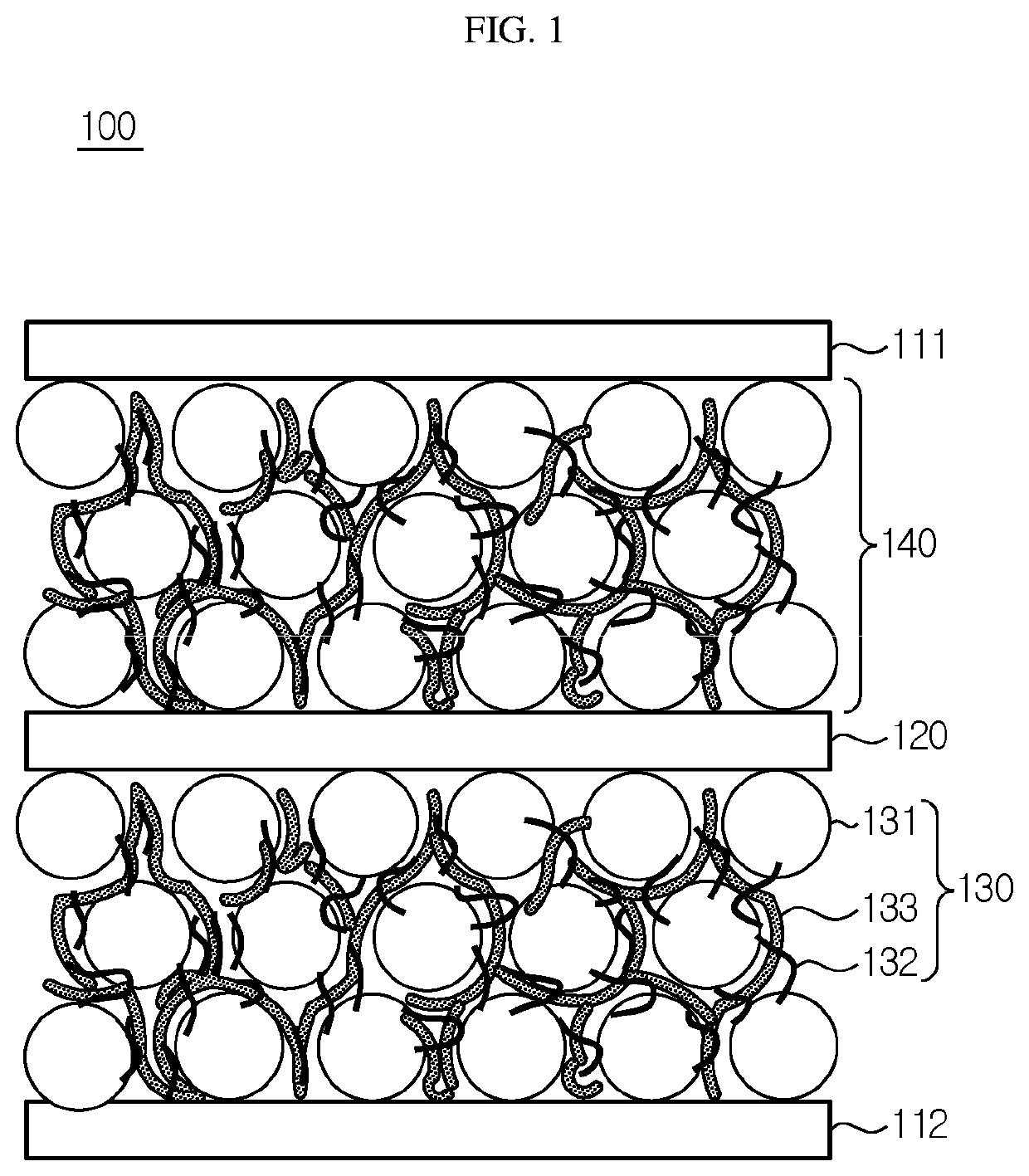
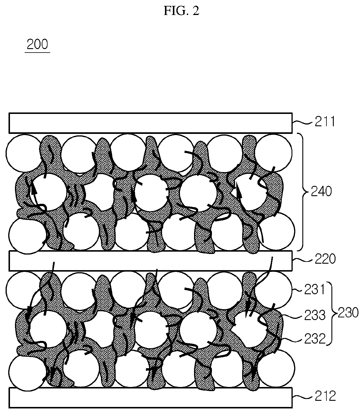
The present electrode design in the all solid-state battery increases the contact area between the electroactive material particles and the polymeric solid electrolyte, resulting in more reaction sites for the electroactive material. The conductive material is also positioned more closely to the periphery of the active material, which increases the contact frequency between the conductive material and the electroactive material particles. This design also increases the contact area between the electrode active material layer and the solid electrolyte membrane, reducing resistance and improving lithium ion transportability during charge / discharge, ultimately increasing the capacity of the battery.

Problems solved by technology

A lithium ion battery using a liquid electrolyte has a structure in which a negative electrode and positive electrode are defined by a separator, and thus may cause a short-circuit when the separator is damaged by deformation or external impact, resulting in a risk, such as overheating or explosion.
Therefore, it can be said that development of a solid electrolyte capable of ensuring safety is a very important problem in the field of lithium ion secondary batteries.
However, a lithium secondary battery using a solid electrolyte has lower ion conductivity as compared to a battery using a liquid electrolyte and particularly shows degradation of output characteristics at low temperature.
In addition, such a solid electrolyte is problematic in that it shows lower surface adhesion to an active material, as compared to a liquid electrolyte, to cause an increase in interfacial resistance, and is distributed while not being in contact with an electrode active material to cause degradation of output characteristics or capacity characteristics as compared to the amount of a conductive material introduced to an electrode.
Thus, the battery shows low capacity and low energy density as compared to the amount of active material introduced thereto.
If severe compression is carried out in order to increase the contact area between the active material particles and the polymeric solid electrolyte, the active material particles may be cracked to generate defects.
Particularly, interfacial contact between the active material layer and the solid electrolyte membrane is insufficient when lithium ions of the electrode passes through the solid electrolyte membrane during charge / discharge, resulting in an increase in resistance, which ultimately adversely affects capacity realization and rate characteristics of the finished battery.

Method used


Image

  • Method for Manufacturing All Solid-State Battery Comprising Polymeric Solid Electrolyte and All Solid-State Battery Obtained Thereby
  • Method for Manufacturing All Solid-State Battery Comprising Polymeric Solid Electrolyte and All Solid-State Battery Obtained Thereby

Examples


example 1

[0088](1) Manufacture of Electrode

[0089]First, NCM811 (LiNi0.8Co0.1Mn0.1O2) as an electrode active material, vapor grown carbon fibers (VGCF) as a conductive material, and a polymeric solid electrolyte (a mixture of polyethylene oxide (PEO) with LiFSI ((LiCF3SO2)2N), molar ratio of PEO:LiFSI, [EO]:[Li+]=20:1) were mixed at a weight ratio of 80:3:17 and the resultant mixture was introduced to acetonitrile, followed by agitation, to provide electrode slurry. An aluminum current collector having a thickness of 20 μm was prepared. The slurry was applied to the current collector by using a doctor blade and the resultant product was vacuum-dried at 120° C. for 4 hours. Then, compression was carried out by using a roll press device to obtain an electrode having a loading amount of 2 mAh / cm2, an electrode active material layer thickness of 48 μm and a porosity of 22%. The porosity means the ratio of volume of pores (pore volume) occupied by pores based on the total volume. The porosity was ...

example 2

[0094]A battery was obtained in the same manner as Example 1, except that solvent annealing was carried out at room temperature. Before solvent annealing, the electrode active material layer of the electrode assembly had a porosity of 22%. After solvent annealing, the electrode active material layer of the electrode assembly had a porosity of 16%.

example 3

[0095]A battery was obtained in the same manner as Example 1, except that solvent annealing was carried out at room temperature for 2 days. Before solvent annealing, the electrode active material layer of the electrode assembly had a porosity of 22%. After solvent annealing, the electrode active material layer of the electrode assembly had a porosity of 13%.


PUM

PropertyMeasurementUnit
porosityaaaaaaaaaa
porosityaaaaaaaaaa
temperatureaaaaaaaaaa

Abstract

The present disclosure relates to an all solid-state battery cell and a method for manufacturing the same. The gaps between the electrode active material particles forming the electrode active material layer are filled with a mixture of a polymeric solid electrolyte with a conductive material, and an organic solid electrolyte membrane is interposed between the positive electrode and the negative electrode. The method comprises a solvent annealing process to improve the contact between the electrode active material particles and the conductive material and to improve the contact between the electrode active material layer and the organic solid electrolyte membrane, thereby providing an all solid-state battery cell with improved ion conductivity and capacity realization.

Description

CROSS-REFERENCE TO RELATED APPLICATIONS[0001]This application is a national phase entry under 35 U.S.C. § 371 of International Application No. PCT / KR2019 / 005377 filed May 3, 2019, which claims priority from Korean Patent Application No. 10-2018-0051476 filed May 3, 2018, all of which are incorporated herein by reference.TECHNICAL FIELD[0002]The present disclosure relates to a method for manufacturing an all solid-state battery comprising a polymeric solid electrolyte and an all solid-state battery obtained thereby.BACKGROUND ART[0003]A lithium ion battery using a liquid electrolyte has a structure in which a negative electrode and positive electrode are defined by a separator, and thus may cause a short-circuit when the separator is damaged by deformation or external impact, resulting in a risk, such as overheating or explosion. Therefore, it can be said that development of a solid electrolyte capable of ensuring safety is a very important problem in the field of lithium ion seconda...

Claims


Application Information

Patent Timeline
Patent Type & Authority Applications(United States)
IPC IPC(8): H01M4/62H01M4/13H01M10/0565H01M10/058
CPCH01M4/62H01M4/13H01M2300/0082H01M10/058H01M10/0565H01M4/02Y02E60/10H01M4/0471H01M4/624H01M2004/021Y02P70/50
Inventor LEE, JUNG-PILKIM, JI-YOUNGRYU, JI-HOONKANG, SUNG-JOONGLEE, JAE-HYUN
Owner LG ENERGY SOLUTION LTD
Learn More