MnO2 ANODE FOR LI-ION AND NA-ION BATTERIES

a rechargeable li-ion and na-ion battery technology, applied in the field of mno2 anodes, mno2 anodes for rechargeable li-ion and na-ion batteries, can solve the problems of increasing cost and time-consuming printing process, increasing the cost and time-consuming of cell manufacturing, and increasing the probability of reversible insertion/desertion of na-ions from the host material, etc., to increase versatility, cost-efficien

Active Publication Date: 2018-11-29
THE HONG KONG POLYTECHNIC UNIV
View PDF1 Cites 4 Cited by
  • Summary
  • Abstract
  • Description
  • Claims
  • Application Information

AI Technical Summary

Benefits of technology

The patent describes a method for making a MnO2 anode for use in batteries, specifically for lithium-ion and sodium-ion batteries. The method involves coating a substrate with MnO2 nanosheets and annealing it at a high temperature for at least 100 minutes. The resulting MnO2 thin films can be used as the anode in batteries, with the substrate being coated using methods such as drop coating, spray printing, or inkjet printing. The MnO2 anode can be annealed at temperatures ranging from 260-320°C for at least 100 minutes. The resulting batteries can have improved performance and longer life.

Problems solved by technology

However, in order to utilise these printing processes, the ink required for all the major components of the batteries, including electrolyte and two electrodes is critical.
However, the electrodes typically produced are vulnerable to common solvents (e.g., water, ethanol and acetone), and suffer from reduced electrical conductivity and require proper substrates, causing an increasing cost and time-consuming printing process, further imposing great challenges on cell manufacturing.
In addition due to about 55% larger in radius of Na ions as compared to Li ions, the reversible insertion / desertion of Na ions from the host materials is expected to be relatively more difficult.
Few materials systems have been reported to date which could serve the anodes for both Li-ion and Na-ion batteries.
However, due to the large specific volume variations and low electrical conductivity, MnO2-based electrodes typically suffer from poor cycling performance and rate capability.
Additives are widely used in battery electrodes (whatever cathode or anode) since many electro-active materials are not able to adhere to the common used substrates by themselves.
However, such binders demonstrate poor electrical conductivity.
Without these additives, conventional electrodes cannot be prepared.
Furthermore, even novel materials generally cannot adhere to the substrates by themselves and the binder and conductive agents are frequently used.
The inclusion of additives increases the cost and complicates the preparation process, as well as greatly decreasing the conductivity of the electrode materials.
Hence, the inclusion of additives is undesirable.
However, these approaches also meet other challenges.
Successful applications of pure MnO2 electrodes (i.e., additive-free MnO2 electrodes) have not been reported due to the large specific volume variations and low electrical conductivity.
Despite mixing with conducting agent, current MnO2-based electrodes still suffer from poor cycling performance and rate capability.

Method used


Image

  • MnO2 ANODE FOR LI-ION AND NA-ION BATTERIES
  • MnO2 ANODE FOR LI-ION AND NA-ION BATTERIES
  • MnO2 ANODE FOR LI-ION AND NA-ION BATTERIES

Examples


example 1

Preparation of a MnO2 Anode on Copper Foil and Stainless Steel

[0100]10 wt % glucose solution was poured into the Teflon-sealed stainless autoclave (e.g., Parr 4748 acid digestion bomb to achieve a scalable production) at 180° C. for 180 minutes. When the reaction was completed, the suspension was poured out for filtration. The residues were collected and re-dissolved into water and sonicated sufficiently to form a 0.1 mg·mL−1 suspension. Then 16 mg·mL−1 KMnO4 solution was added into the suspension dropwise under continuous stirring and maintained at 40° C. for 6 hours. The mass ratio of KMnO4 and carbon was about 8:1. After that the suspension was sealed inside stainless steel autoclave at 100° C. for 4 hours. After cooling to room temperature, the suspension was filtered by using filter membrane (pore size: 2 nanosheets (MnNSs) suspension for spray printing. All chemicals employed were analytical reagents purchased from International Laboratory, USA and were used without further pu...

example 2

Characterization of MnO2 Anode on Copper Foil and Stainless Steel

[0104]Material characterizations are conducted using methods commonly known to a person skilled in the art and as described below.

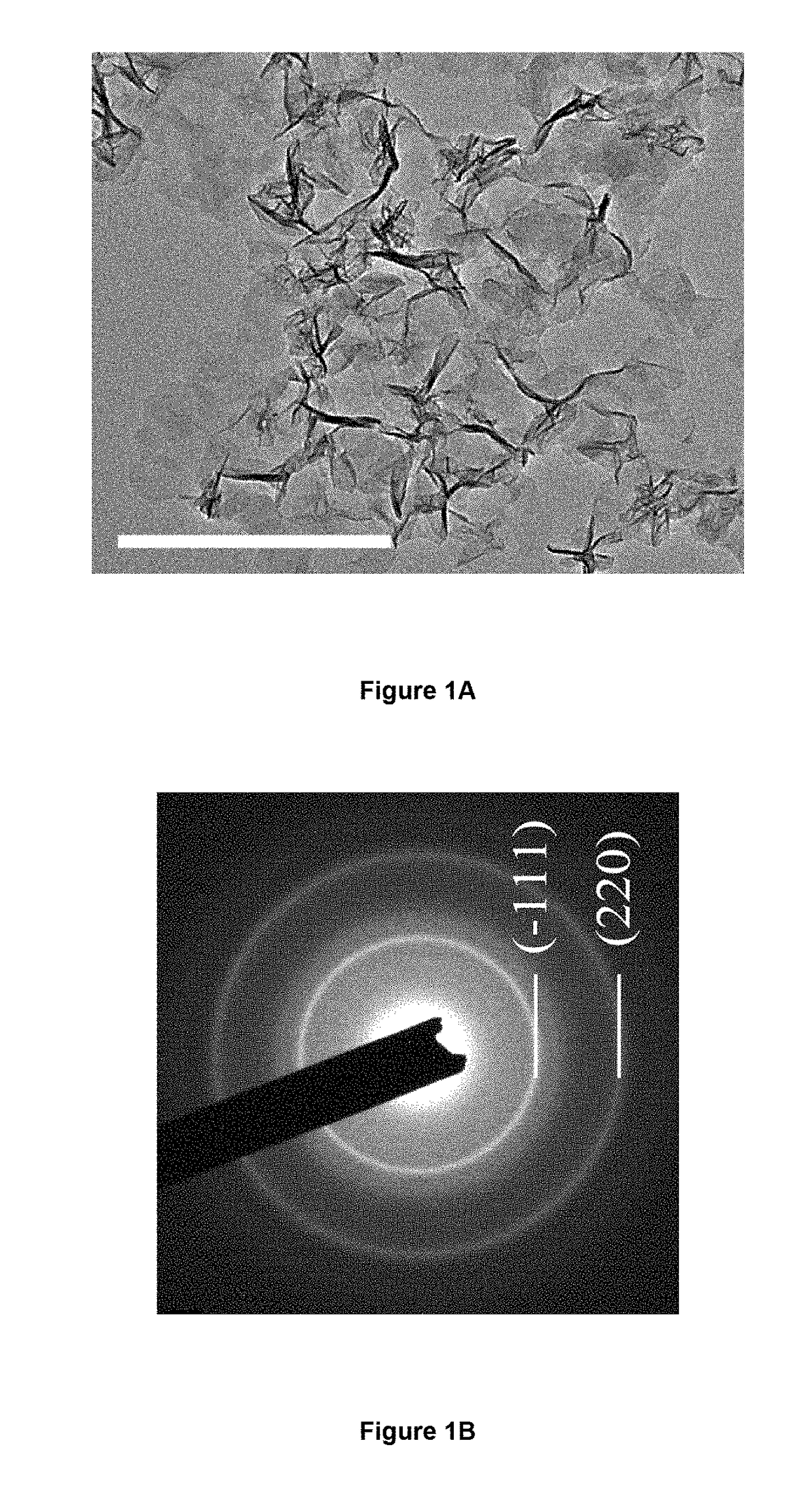
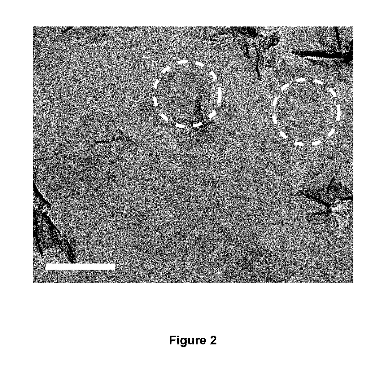
[0105]The surface and cross sectional morphology and the energy-dispersive X-ray spectroscopy (EDX) of the MnO2 thin films were characterized by scanning electron microscopy (SEM) (Tescan MIMA3). TEM images and select area electron diffraction (SAED) pattern were recorded through a JEM 2100F (field emission) scanning transmission electron microscope (spherical aberration Cs: 2.3 mm, Chromatic aberration Cc: 1.0 mm, point resolution 0.23 nm) equipped with an Oxford INCA x-sight EDS Si(Li) detector. XRD pattern was carried out by using a Rigaku SmartLab X-ray diffractometer operating at 45 kV and 200 mA with Cu Kα source (λ=1.54056 Å). Raman spectrum was recorded by using a micro laser Raman spectrometer (DX2, Thermo, λ=532 nm). Atomic force microscopy (AFM) image was recorded by using Digital...

example 3

Preparation of Comparative MnO2-Based Anodes and Comparison with Presently Described Embodiments of the Invention

“CE” Represents Comparative Experimental Example

Preparation of the MnO2 / Nitrogen-Doped Graphene Hybrid Aerogel Composite (“CE-A”)

[0115]The MnO2 / nitrogen-doped graphene hybrid aerogel composites (MNGAs) were fabricated through a facile redox reaction between KMnO4 and carbon within NGHs. In a typical procedure, NGHs were immersed in a solution of 0.1 M KMnO4 / 0.1 M Na2SO4 for 120 minutes. The above mixture was vigorously shaken in a shaker at room temperature to promote the diffusion of KMnO4 / Na2SO4 solution into NGHs and the spontaneous reaction between KMnO4 and carbon in NGHs. After the reaction, the hybrid hydrogels were dialyzed with a great amount of deionized water for 48 h. The final products, MNGAs, were obtained by freeze drying the hybrid hydrogels for 24 h under vacuum.

Preparation of the 3D Porous Graphene / MnO2 Composite (“CE-B”)

[0116]The pretreated macroporous ...


PUM

PropertyMeasurementUnit
diametersaaaaaaaaaa
thicknessaaaaaaaaaa
diameteraaaaaaaaaa

Abstract

In the present invention there is provided an MnO2 anode with improved electrochemical properties, and a method of preparation of an anode, wherein there anode comprises a substrate at least partially coated with MnO2 nanosheets (MnNSs) forming additive free MnO2 thin films. The method includes providing MnO2 nanosheets (MnNSs) suspension with diameters less than 50 nm; printing the MnNSs suspension on substrates to form MnO2 thin films (MnTFs); and annealing the MnTFs at 260-320° C. for at least 100 minutes. Energy storage device comprising the MnO2 anode such as a Na-ion cell, and a Li-ion cell are also described.

Description

TECHNICAL FIELD[0001]The present disclosure generally relates to improved MnO2 anodes, MnO2 anode based rechargeable Li-ion and Na-ion batteries, with improved electrochemical properties, as well as methods of preparation of the MnO2 anodes and batteries.BACKGROUNDDescription of the Related Art[0002]Printable electronics is of great interest in applications ranging from thin film transistors (TFTs), energy storage devices, fuel cells, solar cells to integrated circuits. In particular, printable rechargeable batteries, mainly Li-ion or Na-ion batteries, have attracted attention due to their potential for use in portable electronic devices, wearable electronic clothing and implantable or patchable sensors.[0003]In pursuit of a flexible and reliable power source, advances have been made toward using an all-printable-solution technology to replace the traditional slurry-coating process. To date, widespread mass-printing approaches, such as screen printing, stencil printing and spray pri...

Claims


Application Information

Patent Timeline
Patent Type & Authority Applications(United States)
IPC IPC(8): H01M4/131H01M4/134H01M4/1391H01M4/04H01M4/50H01M4/38H01M4/66H01M10/0525H01M10/054H01M10/0569H01M10/0568H01M2/02
CPCH01M4/131H01M2220/30H01M4/1391H01M4/0404H01M4/0471H01M4/502H01M4/382H01M4/661H01M10/0525H01M10/054H01M10/0569H01M10/0568H01M2/0222H01M2004/027H01M2300/0037H01M2300/0034H01M4/134H01M4/663Y02E60/10
Inventor QIAN, JIASHENGLAU, SHU PING
Owner THE HONG KONG POLYTECHNIC UNIV
Why Eureka
Try Eureka