
3D display apparatus

Inactive Publication Date: 2013-05-30
POPOVICH MILAN MOMCILO +1
View PDF5 Cites 79 Cited by
  • Summary
  • Abstract
  • Description
  • Claims
  • Application Information

AI Technical Summary

Benefits of technology

[0041]In one embodiment of the invention there is further provided means for correcting image distortion.
[0042]In one embodiment of the invention the electronic correction means may be further adapted to independently pre-distort the geometry of each primary color represented by the input image data and generate a pre-distorted primary color image dat

Problems solved by technology

Linearly polarized glasses suffer from the problem that the viewer's head must be kept level to avoid tilting of the viewing filters causing left and right images images to bleed over to the opposite channel.
Traditional audio visual communication systems such as video conferencing suffer from the problem that cameras, monitors, electrical cabling and other equipment provide an unnatural environment that is not invisible enough to allow relaxed hu

Method used


Image

  • 3D display apparatus
  • 3D display apparatus
  • 3D display apparatus

Examples


Embodiment Construction

[0100]There is requirement for a cost-effective, optically efficient color sequential illuminator that provides alternating beams of orthogonally polarized illumination light.

[0101]There is a further requirement for an image generator that projects alternating orthogonally polarized left and right eye images onto a screen for stereoscopic viewing through a pair of glasses containing a pair of orthogonal polarizing filters.

[0102]There is a further requirement for a cost effective, efficient projection screen for displaying said alternating orthogonally polarized left and right eye images wherein the screen incorporates means for capturing a full colour stereoscopic image of the viewer.

[0103]There is a further requirement for a cost effective, efficient projection screen for displaying said alternating orthogonally polarized left and right eye images wherein the screen further incorporates means for head and eye tracking.

[0104]It will be apparent to those skilled in the art that the p...


PUM


Abstract

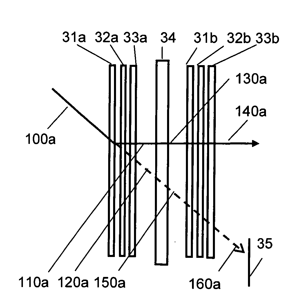
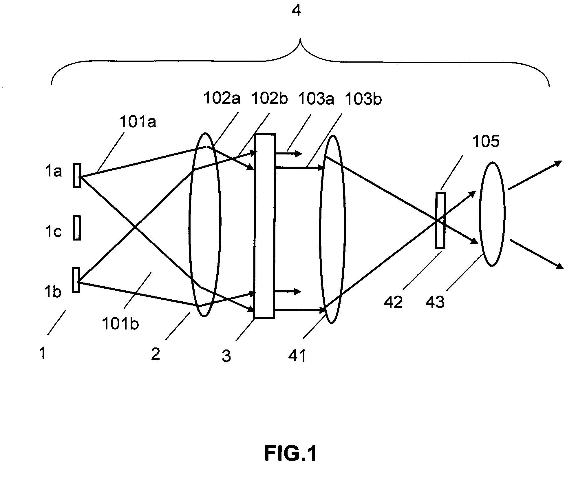
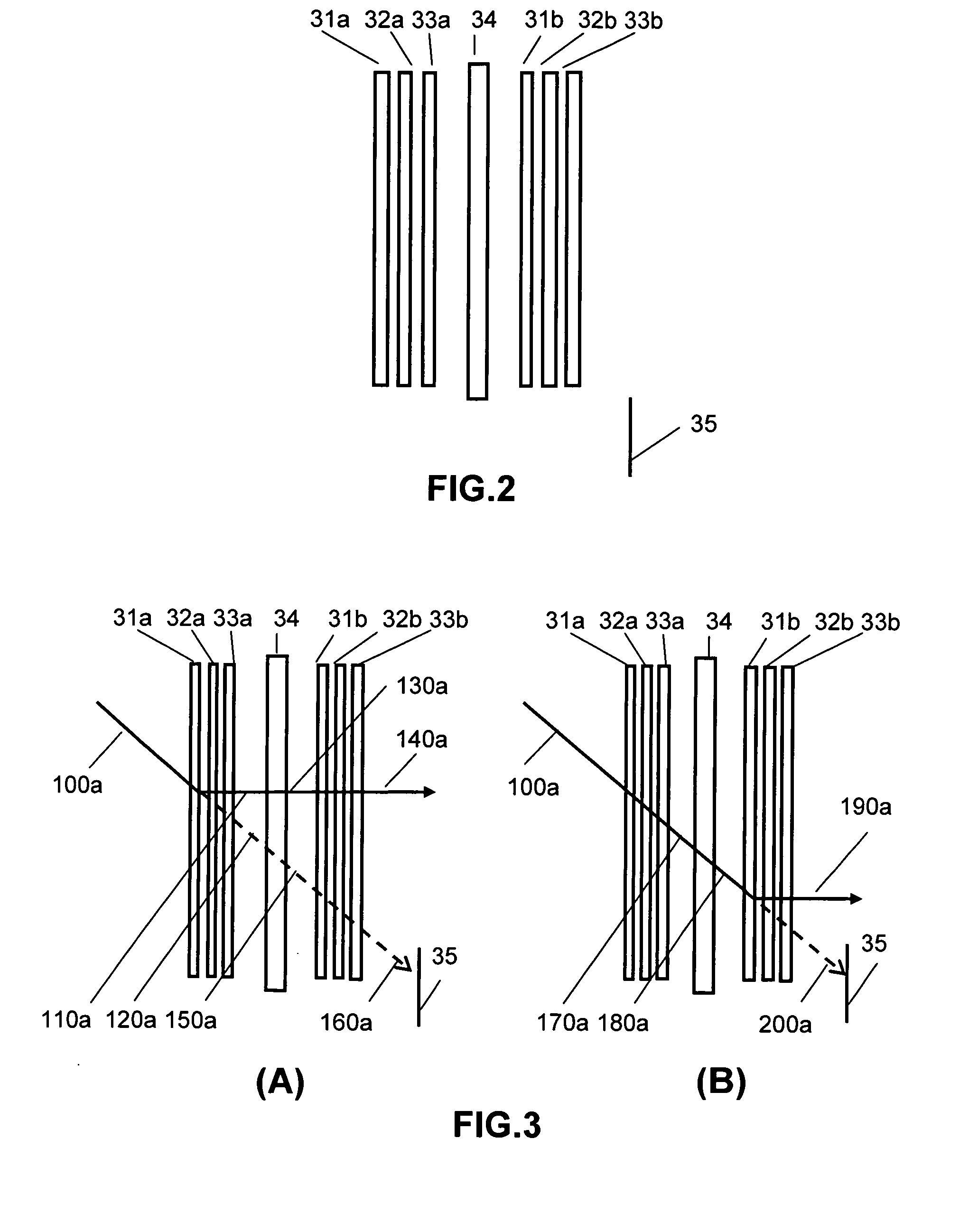
A 3D display is provided comprising at least one light source, a Switchable Bragg Grating device, a microdisplay and a projection lens system. In one embodiment of the invention the SBG device converts the source light into colour sequential illumination and, and provides sequential orthogonally polarized illumination of the microdisplay for each colour. In one embodiment of the invention the first SBG device converts the source light into colour sequential illumination and, and provides sequential first and second sense circularly polarized illumination. The microdisplay is updated with alternating left and right eye perspective images for stereoscopic viewing.

Description

REFERENCE TO PRIORITY APPLICATION[0001]This application claims the priority of U.S. Provisional Patent Application No. 61 / 213,303 filed on 28 May 2009.REFERENCE TO EARLIER APPLICATIONS[0002]This application incorporates by reference in their entireties U.S. Pat. No. 6,115,152, issued 5 Sep. 2000 entitled “HOLOGRAPHIC ILLUMINATION SYSTEM”; the PCT application: PCT / US2006 / 041689 entitled “COMPACT HOLOGRAPHIC ILLUMINATION DEVICE” with international filing date 27 Oct. 2006; and PCT application PCT / IB2008 / 0019099 with International Filing date 22 Jul. 2008 entitled LASER ILLUMINATION DEVICES”.BACKGROUND OF THE INVENTION[0003]This invention relates to 3D visual displays and more specifically to an apparatus for providing left and right eye illumination for a 3D display.[0004]Three-dimensional image displays create the illusion of depth by providing a slightly different perspective image to each eye. The brain fuses the images to create a three dimensional images. The left and right image...

Claims


Application Information

Patent Timeline
IPC IPC(8): G02B27/26G02B27/48G03B21/28G02B27/28G03B21/14G02B30/25H04N13/363H04N13/39
CPCG02B27/26G03B35/26G02B27/48G03B21/28G06F3/013H04N13/0468G02B27/0093H04N13/0422H04N13/0425H04N13/0431H04N13/0434H04N13/0459G06F3/012G03B21/2033G03B21/2073G03B33/08G02B27/283H04N13/337H04N13/324H04N13/334H04N13/363H04N13/366H04N13/327G02B30/25H04N13/39
Inventor POPOVICH, MILAN MOMCILOWALDERN, JONATHAN DAVID
Owner POPOVICH MILAN MOMCILO
Learn More