
Multi-layered water-splitting photocatalyst having a plasmonic metal layer with optimized plasmonic effects

Inactive Publication Date: 2018-11-08
SABIC GLOBAL TECH BV
View PDF3 Cites 3 Cited by
  • Summary
  • Abstract
  • Description
  • Claims
  • Application Information

AI Technical Summary

Benefits of technology

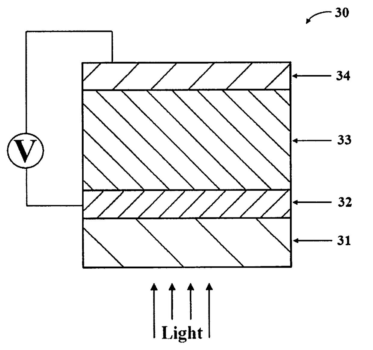
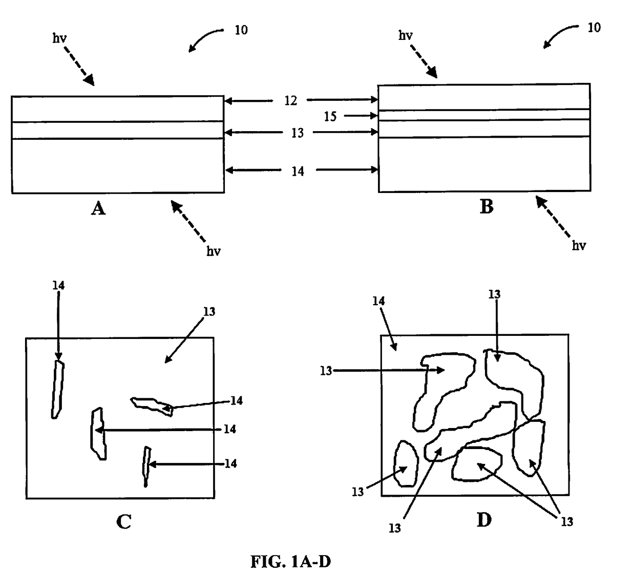
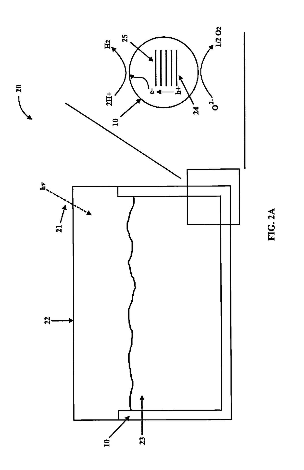
The patent text describes a solution for improving the efficiency of water-splitting photocatalysts. By using plasmonic metals as films or layers with a thickness range of 2 nanometers to 20 nanometers, the metals can optimize hydrogen production during water splitting reactions. The optimal thickness range results in an increased electric field when subjected to ultraviolet and visible light. The use of doping agents, conductive metal nanoparticles, and sacrificial agents can be further reduced or eliminated. The patent also describes a water-splitting system for generating hydrogen from water, which includes a container / reaction vessel and multiple photocatalysts. The photocatalysts can be coated onto the surface of the reaction vessel's walls or placed on a substrate or support structure. The system can also include a light source, such as sunlight or an artificial light source. The "proximal" refers to the plasmonic metal layer being in direct contact with the photoactive layer or within a sufficient distance of the photoactive layer to assist in the promotion of excited electrons and holes to the surface of the photoactive layer.

Problems solved by technology

While methods currently exist for producing hydrogen from water, many of these methods can be costly, inefficient, or unstable.
With respect to photocatalytic electrolysis of water from light sources, while many advances have been achieved in this area, most materials are either unstable under realistic water splitting conditions or require considerable amounts of other components (e.g., large amounts of sacrificial hole or electron scavengers) to work, thereby offsetting any gained benefits.
One of the main limitations of most photocatalysts is the fast electron-hole recombination, a process that occurs at the nanosecond scale, while the oxidation-reduction reactions are much slower (microsecond time scale).
Problems associated with these types of systems include light absorption efficiency, charge carrier life time, and materials stability.
Ultimately, however, over 90% of photo-excited electron-hole pairs disappear / recombine prior to performing the desired water splitting reaction, thereby making the currently available photocatalysts inefficient (See, for example, Yamada, et al., Appl Phys Lett., 2009, Vol. 95, pp.
While incremental increases in photactive efficiency has been observed, the current photocatalysts remain largely inefficient for large-scale commercial use.

Method used


Image

  • Multi-layered water-splitting photocatalyst having a plasmonic metal layer with optimized plasmonic effects
  • Multi-layered water-splitting photocatalyst having a plasmonic metal layer with optimized plasmonic effects
  • Multi-layered water-splitting photocatalyst having a plasmonic metal layer with optimized plasmonic effects

Examples


example 1

Production and Characterization of Photocatalysts of the Present Invention

[0062]The photocatalytic materials were fabricated on glass substrates. First glass slides were cleaned by ultra-sonication in acetone, ethanol and DI water. Thin Au films were deposited on these glass slides by thermal evaporation in a vacuum chamber. The deposition was done at room temperature with a constant deposition rate of 0.2 A° / s. To prepare the photocatalyst, anatase TiO2 (supplier: Hombikat) with an average particle size of about 7 nm and BET surface area of about 320 m2 / g was impregnated with PdCl2 salt solution. Excess water was evaporated to dryness under constant stirring with slow heating at 80° C. The dried photocatalysts was calcined at 350° C. for 5 hours. The resulting photo-catalysts with 0.4 wt % Pd loading on anatase TiO2 had an average particle size of about 10-12 nm and BET surface area of approximately 120 m2 / g. Similarly, comparative devices using non-plasmonic metal films (platinum ...

example 2

Photocatalytic Activity of the Photocatalysts of the Present Invention

[0067]Photocatalytic reactions were evaluated in a 190 mL volume quartz reactor. 30 mL of 5 vol % glycerol aqueous solution was used to evaluate the water splitting activity. The coated slides were inserted vertically into the reactor and the reactor was purged with N2 gas to remove any O2. The photoreactions were carried out using a Xenon lamp (Asahi spectra MAX-303) at a distance of 9 cm from the reactor with a total UV flux of 5-6 mW / cm2 in the 280-380 nm range. Product analysis was performed by gas chromatograph (GC) equipped with thermal conductivity detector (TCD) connected to Porapak Q packed column (2 m) at 45° C. and N2 was used as a carrier gas.

[0068]The H2 production rates of the photocatalysts of the present invention under UV and visible light excitation (280-650 nm) is presented in in FIG. 6. The photocatalytic activity was stable and reproducible. Pure anatase TiO2 with 0.4 wt. % Pd loading, showed ...

example 3

Electric Field Enhancement of the Photocatalysts of the Present Invention

[0071]To identify the mechanism of how the LSPR helps enhancing the photocatalytic activity, optical simulations of TiO2 on Au films as a function of thickness was conducted using commercial software, COMSOL Multiphysics version 4.4., in RF module. COMSOL uses finite element method (FEM) to solve Maxwell's equations for the specific electromagnetic wave condition and gives electrical field intensity (|E|2) as an output. The incident electromagnetic field was taken as 1 V / m; with wavelength of incident, electromagnetic field set to be at 500 nm and polarized in the y-direction. The incident electromagnetic field was set normal to the Au films or glass substrate. Dielectric permittivity of Au was taken from Johnson-Christy report and the Au island size for 2, 4 and 8 nm Au discontinuous films was taken from the collected SEM images while continuous films were assumed for 12, 16 and 20 nm thickness. The optical si...


PUM

PropertyMeasurementUnit
Fractionaaaaaaaaaa
Thicknessaaaaaaaaaa
Thicknessaaaaaaaaaa

Abstract

Photocatalysts and methods of using the same for producing hydrogen and oxygen from water are disclosed. The photocatalysts include a photoactive layer having a thickness of 10 nanometers (nm) to 1000 nm and a plasmonic metal layer having a thickness of 2 nm to 20 nm and having surface plasmon resonance properties in response to ultra-violet and / or visible light, wherein the plasmonic metal layer is positioned proximal to the photoactive layer.

Description

CROSS REFERENCE TO RELATED APPLICATIONS[0001]This application claims the benefit of priority of U.S. Provisional Patent Application No. 62 / 255,607, filed Nov. 16, 2015, which is hereby incorporated by reference in its entirety.BACKGROUND OF THE INVENTION[0002]A. Field of the Invention[0003]The invention generally concerns a multi-layered photocatalyst that can be used to produce hydrogen from water in photocatalytic reactions. The photocatalyst includes a photoactive layer positioned proximal to a plasmonic metal layer, wherein the plasmonic metal layer has a thickness range of 2 nm to 20 nm to optimize its plasmonic resonance properties in response to ultra-violet and / or visible light.[0004]B. Description of Related Art[0005]Hydrogen production from water offers enormous potential benefits for the energy sector, the environment, and the chemical industry (See, for example, Kodama & Gokon, Chem. Rev., 2007, Vol. 107, p. 4048; Connelly & Idriss, Green Chemistry, 2012, Vol. 14, p. 260...

Claims


Application Information

Patent Timeline
IPC IPC(8): B01J23/52B01J23/42B01J21/06B01J21/08B01J35/00B01J37/02B01J19/12B01J7/02C01B3/04C23C14/18C25B1/00C25B11/04
CPCB01J23/52B01J23/42B01J21/063B01J21/08B01J35/0006B01J35/0013B01J35/004B01J37/0244B01J19/127B01J19/123B01J7/02C01B3/042C23C14/185C25B1/003C25B11/0484B01J2219/1203B01J2219/0892B01J2219/0877B01J23/44C01B13/0207C23C14/18B01J37/0238B01J37/0248B01J37/343B01J37/0219B01J37/0217Y02E60/36C25B1/55C25B11/093B01J35/396B01J35/393B01J35/30B01J35/23B01J35/40B01J35/615B01J35/39B01J35/19
Inventor KHAN, MOHD ADNANAL-OUFI, MAHERIDRISS, HICHAM
Owner SABIC GLOBAL TECH BV
Learn More