
Silicon/germanium nanoparticle inks, laser pyrolysis reactors for the synthesis of nanoparticles and associated methods

a technology of nanoparticles and inks, which is applied in the field of inorganic nanoparticle synthesis, can solve the problems of corresponding increase in the market of solar cells, and achieve the effect of reducing the exposure to metal contaminants

Inactive Publication Date: 2013-08-29
NANOGRAM
View PDF5 Cites 1 Cited by
  • Summary
  • Abstract
  • Description
  • Claims
  • Application Information

AI Technical Summary

Benefits of technology

The approach enables the production of high-purity silicon / germanium nanoparticles with precise dopant levels, facilitating the formation of semiconductor devices and solar cells while simplifying processing and reducing contamination.

Problems solved by technology

Also, with increasing energy costs and increasing demand for energy, the market for solar cells has been correspondingly increasing.

Method used


Image

  • Silicon/germanium nanoparticle inks, laser pyrolysis reactors for the synthesis of nanoparticles and associated methods
  • Silicon/germanium nanoparticle inks, laser pyrolysis reactors for the synthesis of nanoparticles and associated methods
  • Silicon/germanium nanoparticle inks, laser pyrolysis reactors for the synthesis of nanoparticles and associated methods

Examples


example 1

Synthesis of Highly Doped Si Nanoparticles Using Laser Pyrolysis with Rectangular Nozzle and Air Knife Quenching

[0225]This example demonstrates the ability to synthesize highly doped silicon nanoparticles with high uniformity using laser pyrolysis.

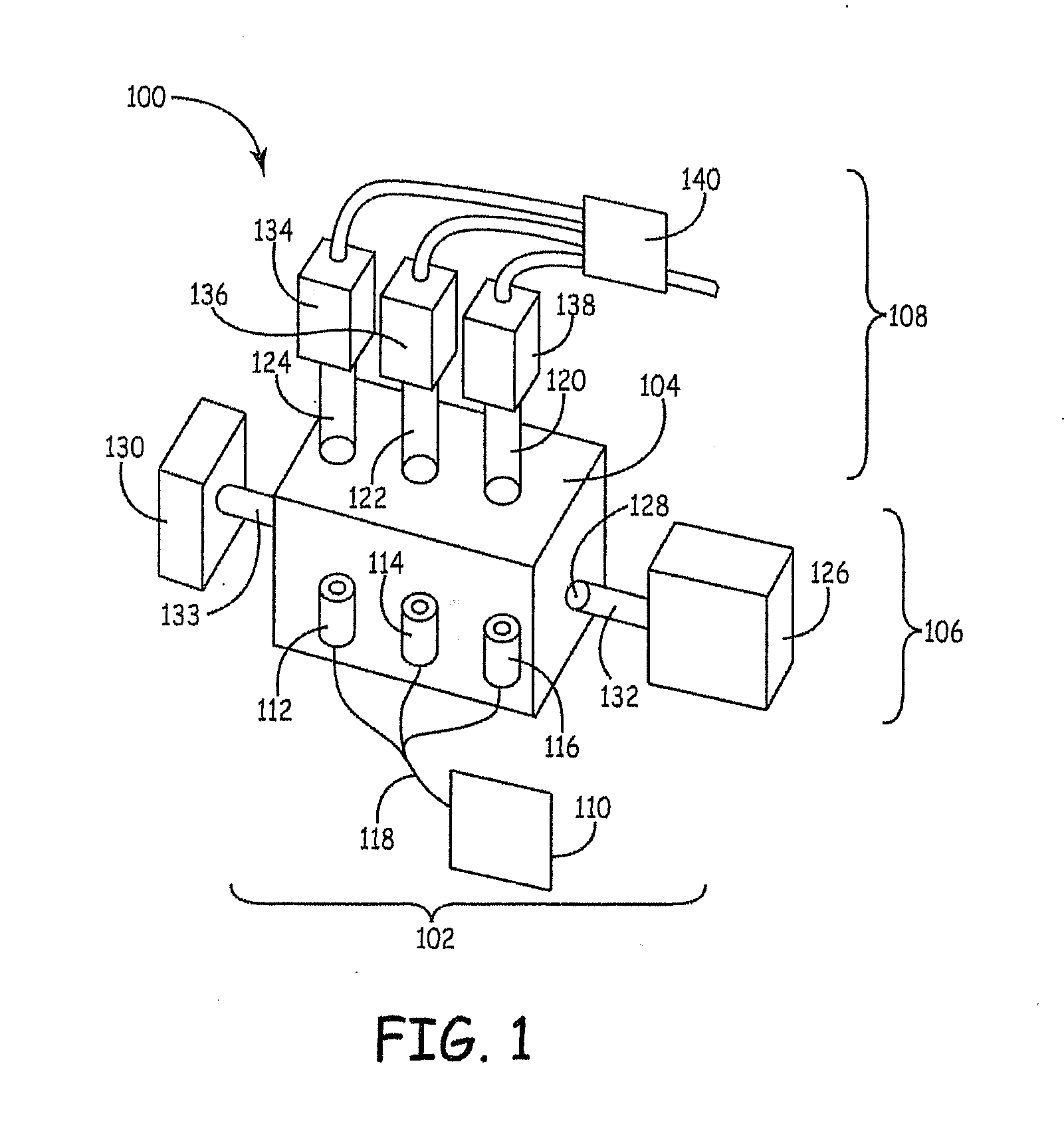
[0226]A laser pyrolysis apparatus similar to FIG. 8 of published U.S. patent application 2009 / 0020411A to Holunga et al., entitled “Laser Pyrolysis With In-Flight Particle Manipulation for Powder Engineering,” incorporated herein by reference. The apparatus was equipped with an air knife to provide quenching of the particles entering the exhaust conduit.

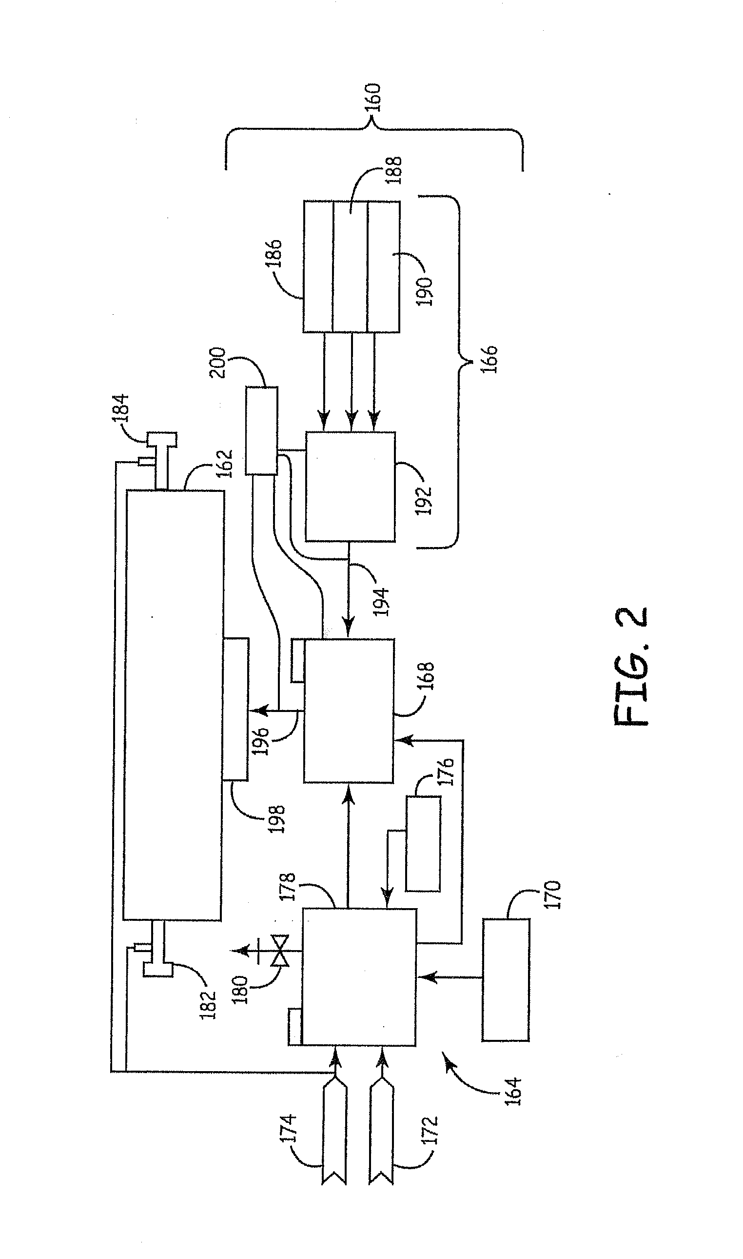
[0227]Phosphine (PH3) was used as the phosphorous dopant source, and the phosphine gas was mixed with inert argon at a mole ratio of 91% Ar to 9% PH3. The silane precursor was mixed with the blend of Ar and phosphine precursor for delivery to the nozzle. A reactant delivery system similar to the system shown in FIG. 2 was used. The parameters for the synthesis of particles with two dopant l...

example 2

Synthesis of Highly N-Doped Si Nanoparticles Using Laser Pyrolysis with Annular Nozzle

[0229]This example demonstrates the ability to synthesize highly doped silicon nanoparticles with high uniformity using laser pyrolysis.

[0230]The apparatus was modified with a nozzle essentially as shown in FIGS. 3-6. Inert shielding gas was flowed through the inner tube and the central annular passage, and the silicon precursor (SiH4) and dopant precursor were flowed through the inner annular passage. Inert gas as an entrainment gas was flowed through the outer annular passage. Experiments were performed targeting different dopant levels.

[0231]As in example 1, phosphine (PH3) was used as the phosphorous dopant source, and the phosphine gas was mixed with inert argon at a mole ratio of 91% Ar to 9% PH3. The silane precursor was mixed with the blend of Ar and phosphene precursor for delivery to the nozzle. A reactant delivery system similar to the system shown in FIG. 2 was used. The parameters for ...

example 3

Synthesis of Boron Doped Si Nanoparticles Using Laser Pyrolysis with Annular Nozzle

[0235]This example demonstrates the ability to synthesize p-doped silicon nanoparticles with high uniformity using laser pyrolysis.

[0236]The laser pyrolysis was performed with an apparatus equipped with a nozzle essentially as shown in FIGS. 3-6. Inert shielding gas was flowed through the inner tube and the central annular passage, and the silicon precursor (SiH4) and dopant precursor were flowed through the inner annular passage. Inert gas as an entrainment gas was flowed through the outer annular passage. Experiments were performed targeting different dopant levels with one sample having a high boron dopant level and another sample having a low boron dopant level.

[0237]Diborane (B2H6) was used as the borane dopant source, and the diborane gas was mixed with inert argon at a selected mole ratio as indicated in the table below. The silane precursor was mixed with the blend of Ar and diborane precursor...


PUM

PropertyMeasurementUnit
average primary particle diameteraaaaaaaaaa
weight percentaaaaaaaaaa
average primary particle diameteraaaaaaaaaa

Abstract

Laser pyrolysis reactor designs and corresponding reactant inlet nozzles are described to provide desirable particle quenching that is particularly suitable for the synthesis of elemental silicon particles. In particular, the nozzles can have a design to encourage nucleation and quenching with inert gas based on a significant flow of inert gas surrounding the reactant precursor flow and with a large inert entrainment flow effectively surrounding the reactant precursor and quench gas flows. Improved silicon nanoparticle inks are described that has silicon nanoparticles without any surface modification with organic compounds. The silicon ink properties can be engineered for particular printing applications, such as inkjet printing, gravure printing or screen printing. Appropriate processing methods are described to provide flexibility for ink designs without surface modifying the silicon nanoparticles.

Description

CROSS REFERENCE TO RELATED APPLICATIONS[0001]This application is a continuation of copending U.S. patent application Ser. No. 13 / 070,286 to Chiruvolu et al. filed Mar. 23, 2011, entitled “Silicon / Germanium Nanoparticle Inks, Laser Pyrolysis Reactors for the Synthesis of Nanoparticles and Associated Methods”, which claims priority to copending U.S. provisional patent application 61 / 359,662 filed Jun. 29, 2010 to Chiruvolu et al., entitled “Silicon / Germanium Nanoparticle Inks, and Associated Methods,” incorporated herein by reference.FIELD OF THE INVENTION[0002]The invention pertains to the synthesis of inorganic nanoparticles, such as doped silicon nanoparticles, with a desirable nozzle design for a laser pyrolysis reactor. The invention further pertains to silicon nanoparticle dispersions that can be formulated as desirable inks, such as inkjet inks, gravure printing inks or printing pastes.BACKGROUND OF THE INVENTION[0003]Silicon is an important commercial material. Many applicatio...

Claims


Application Information

Patent Timeline
Patent Type & Authority Applications(United States)
IPC IPC(8): C09D5/24C09D7/80H10K99/00
CPCB01J2219/0869Y02E10/548B01J2219/0875B82Y30/00C08K3/08C08K3/36C08K9/02C09D7/1266C09D7/1275C09D7/14C09D11/101C09D11/52H01L21/02532H01L21/02573H01L21/02579H01L21/02581H01L21/02601H01L21/02628B01J19/121Y02E10/52C09D5/24H01L31/00H01L31/02363H01L31/03682H01L31/03762H01L31/0747H01L31/182H01L31/1864H01L23/4828H01L23/53276Y02E10/546B01J2219/0871B01D21/262C01B33/02C09D11/03C09D11/033C09D11/037C09D11/322C09D11/36H01L2924/0002H01L2924/00C09D7/67C09D7/68C09D7/80Y02P70/50B01J13/00B01J19/08C01G17/00C09D11/00B82Y40/00C09D11/38
Inventor CHIRUVOLU, SHIVKUMARALTMAN, IGORFREY, BERNARD M.LI, WEIDONGLIU, GUOJUNLYNCH, ROBERT B.PENGRA-LEUNG, GINA ELIZABETHSRINIVASAN, UMA
Owner NANOGRAM
Learn More