Method for manufacturing metal parts and molds and micro-roller used therefor
a technology of molds and metal parts, which is applied in the field of manufacturing a part and a mold and a micro-roller, can solve the problems of severe affecting modeling performance and accuracy, and achieve the effects of improving the formability of complex shape parts, improving the accuracy of side surfaces, and improving the formability and organizational performance of fused deposition layers
- Summary
- Abstract
- Description
- Claims
- Application Information
AI Technical Summary
Benefits of technology
Problems solved by technology
Method used
Image
Examples
example 1
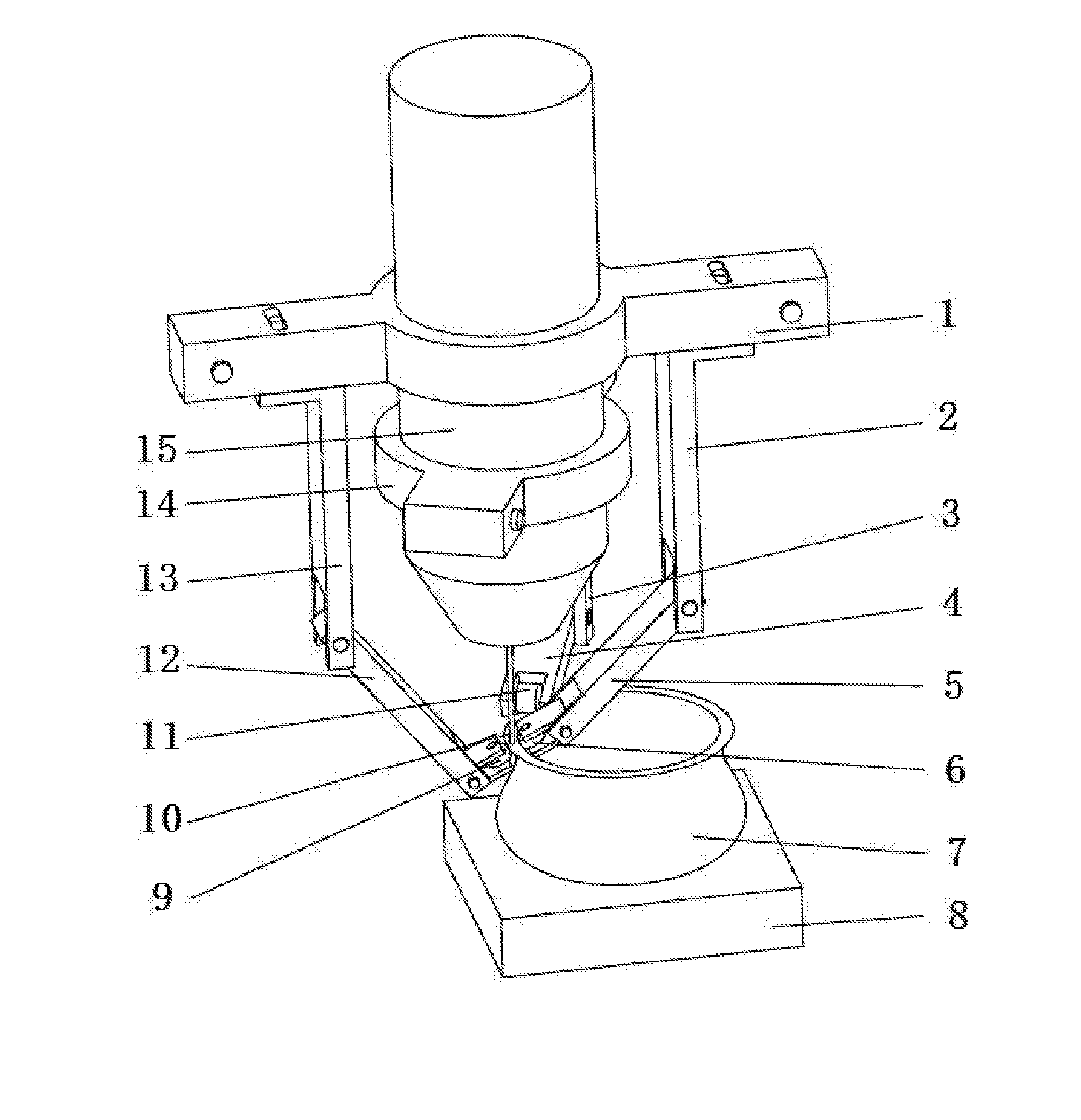
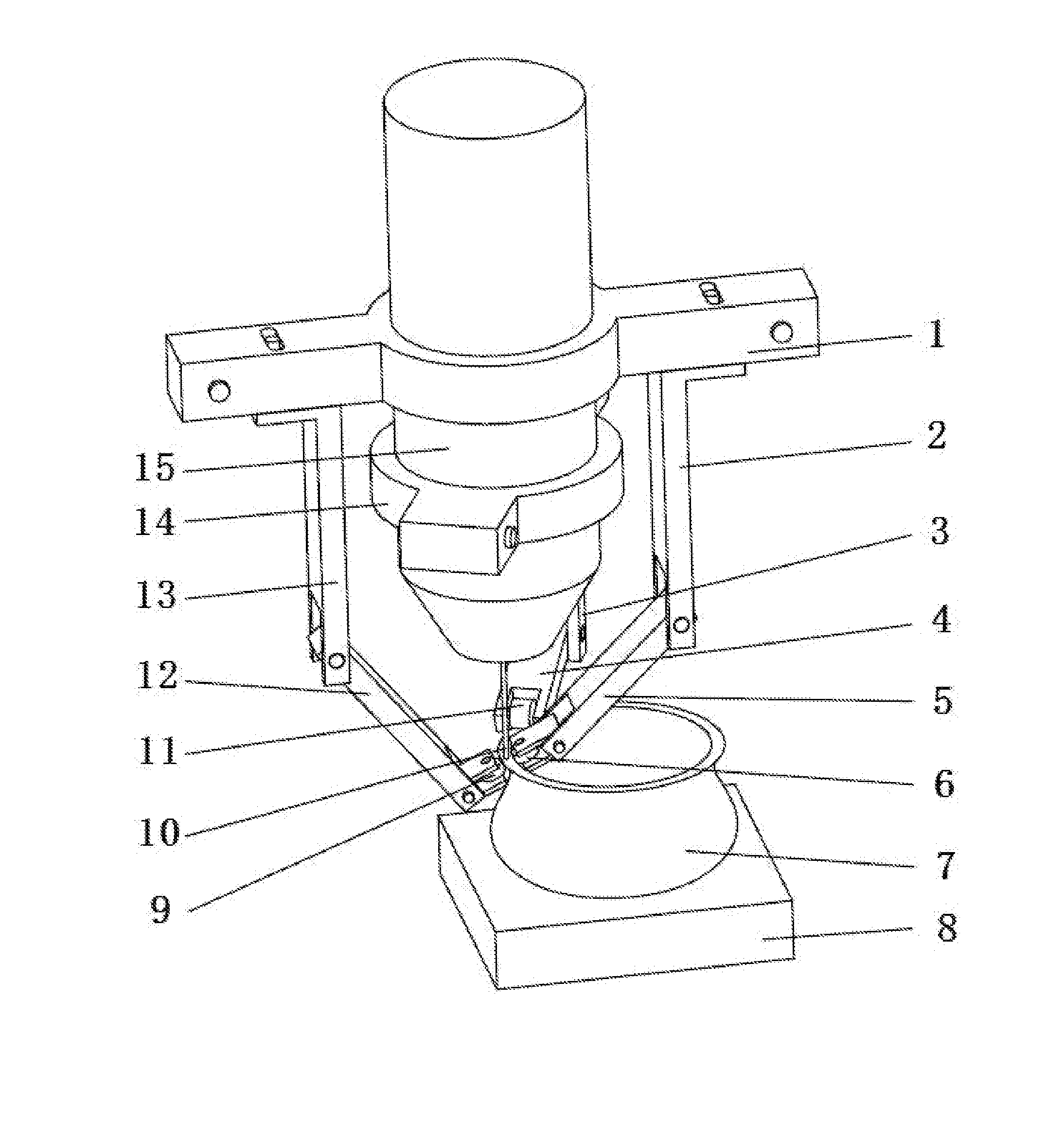
[0029]In the example, a TIG welding gun is used. The micro-roller fixed on the plasma welding gun move synchronously with the welding gun and the side vertical roller follows on the side of the melted and softened area. The welding current of the TIG welding gun is 60 A and uses a Fe—Ni—Cr alloy powder according to the operational performance requirements of the mold cavity to be fused deposition. According to the digital modeling path generated by the 3D CAD model of the mold, the fused deposition modeling and the shaping compressed by the micro-roller operation is synchronously excused layer by layer on the base. If the mold cavity is complex, a surface finishing process will be needed in the modeling process. Therefore, a milling and polishing operation is excused layer by layer or multi-layered segmented during the modeling process according to the milling and polishing path composited with the modeling path. This finishing process is excused alternately with the modeling proces...
example 2
[0030]In the example, a metal gas-shielded welding gun is used. The micro-extrusion unit fixed on the welding gun moves synchronously with the welding gun and the clamping plate follows on the side of the melted and softened area. The welding current of the metal gas-shielded welding gun is 50 A and uses an aluminum alloy wire material. According to the digital modeling path generated by the 3D CAD model of the part, the fused deposition modeling and the shaping compressed by the micro-extrusion unit operation is synchronously excused layer by layer on the base. Based on the requirements of the refinement of the grains and the development of the organizational performance, this compound field modeling process can be performed under vibration condition. Regarding a complex shape region of the part, a milling and polishing operation is excused alternatively during the synchronic process according to the milling and polishing path composited with the modeling path, until the modeling p...
example 3
[0031]In the example, a solid laser of 1000 W power is used. The micro-roller fixed on the laser head move synchronously with the laser head, so that the side vertical roller follows on the side of the melted and softened area and the horizontal roller with hole flexibly tracks the semi-solid softened area near the rear of the welding pool. According to the digital modeling path generated by the 3D CAD model of the part, the laser fused deposition modeling and the shaping compressed by the micro-roller operation is synchronously excused layer by layer on the base to process the high-temperature alloy part. If the part shape is complex, finishing process will be needed in the modeling process. Therefore, a milling and polishing operation is excused layer by layer or multi-layered segmented during the modeling process according to the milling and polishing path composited with the modeling path. This finishing process is excused alternately with the modeling process, until the modelin...
PUM
| Property | Measurement | Unit |
|---|---|---|
| Surface | aaaaa | aaaaa |
Abstract
Description
Claims
Application Information
 - R&D
- Intellectual Property
- Life Sciences
- Materials
- Tech Scout
- Unparalleled Data Quality
- Higher Quality Content
- 60% Fewer Hallucinations
Browse by: Latest US Patents, China's latest patents, Technical Efficacy Thesaurus, Application Domain, Technology Topic, Popular Technical Reports.
© 2025 PatSnap. All rights reserved.Legal|Privacy policy|Modern Slavery Act Transparency Statement|Sitemap|About US| Contact US: help@patsnap.com


