Eureka AIR delivers breakthrough ideas for toughest innovation challenges, trusted by R&D personnel around the world.

Light pattern exposure method, photomask, and photomask blank

a light pattern and exposure method technology, applied in the field of light pattern exposure, can solve the problems of damage to the mask, damage to the photomask, and damage to the other side of the haze, and achieve the effect of inhibiting the degradation of pattern size variation and sufficient etching selectivity ratio

Active Publication Date: 2013-05-23
TOPPAN PHOTOMASK CO LTD +1
View PDF1 Cites 4 Cited by
  • Summary
  • Abstract
  • Description
  • Claims
  • Application Information

AI Technical Summary

Benefits of technology

The optical film made of transition metal / silicon base material has several benefits. Firstly, it helps to stabilize the size of patterns created by a laser during the manufacturing process. This is important because it ensures consistent performance of the product. Secondly, the film also helps to improve the selectivity of the etching process. This means that even if there are defects on the mask, the film can still protect the underlying layers from being damaged during the etching process. The patent text explains how the film works to achieve these benefits and how it can be used in the manufacturing process to improve product performance and reliability.

Problems solved by technology

The lithography using ArF excimer laser light of greater energy was found to cause damages to the mask, which were not found with KrF excimer laser light.
One problem is that on continuous use of the photomask, foreign matter-like growth defects form on the photomask.
Nevertheless, as the dose of ArF excimer laser light irradiated for pattern transfer increases, the photomask is given damages other than haze.
This problem is that as the cumulative irradiation energy dose increases during long-term irradiation of ArF excimer laser light, a layer of a substance which is considered to be an oxide of the pattern material grows outside the film pattern, whereby the pattern width changes.
It is reported that the mask once damaged cannot be restored by cleaning with SC-1 (aqueous ammonia / aqueous hydrogen peroxide) as used in the above-mentioned haze removal or with sulfuric acid / aqueous hydrogen peroxide.

Method used


Image

  • Light pattern exposure method, photomask, and photomask blank
  • Light pattern exposure method, photomask, and photomask blank

Examples


examples

[0073]Experiments are given below for further illustrating the invention although the invention is not limited thereto.

Experiments 1 to 9

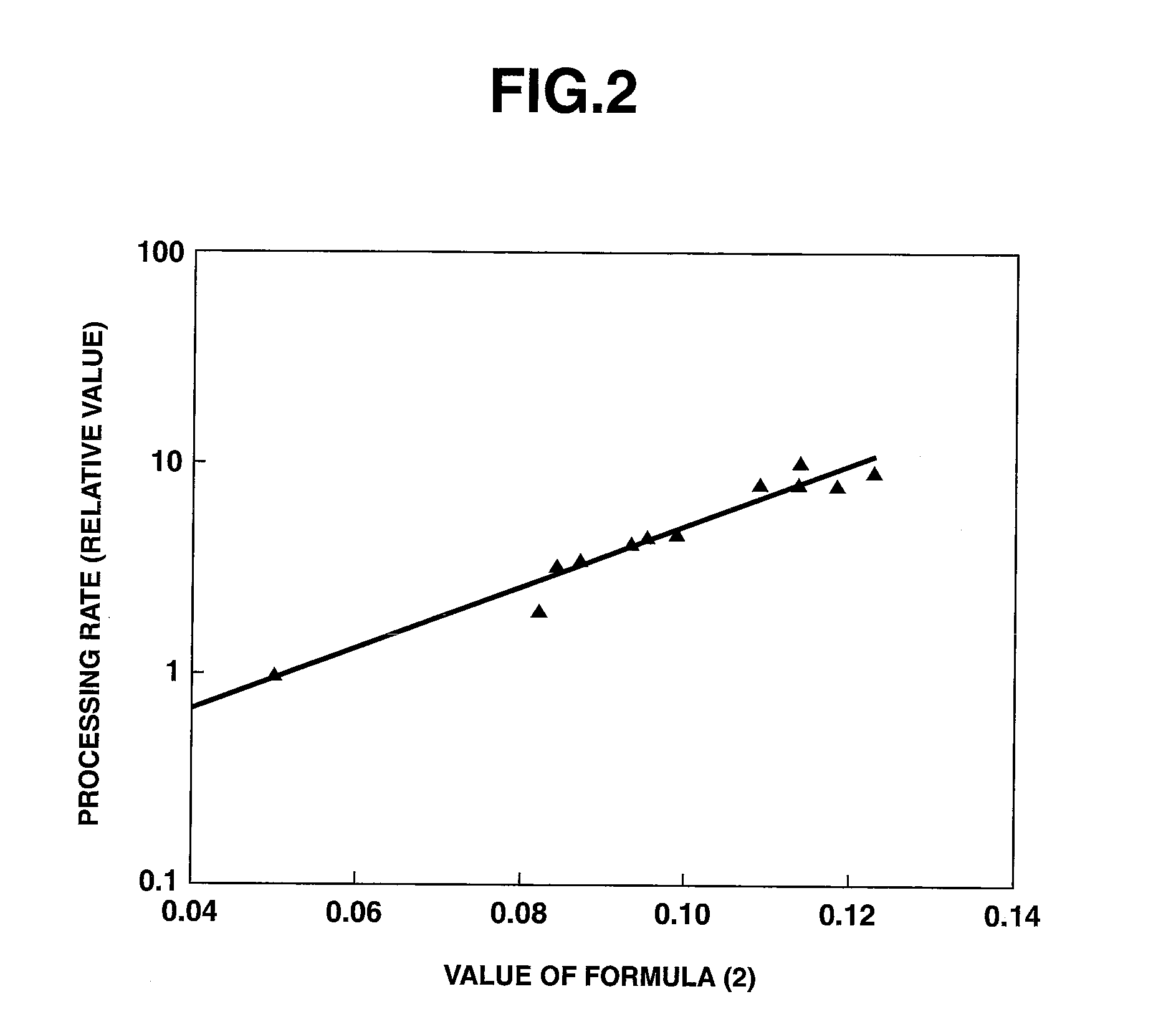
[0074]A DC sputtering system was loaded with two targets, a MoSi2 target and a Si target, and Ar gas, O2 gas and N2 gas were fed thereto as sputtering gas. While a quartz substrate was spun at 30 rpm, a single layer consisting of molybdenum, silicon, nitrogen, and optional oxygen was deposited on the substrate to form a transition metal / silicon base material film (molybdenum / silicon base material film) of about 70 nm thick as a halftone phase shift film. The composition of these 9 transition metal / silicon base material films except for a sub-surface region that extended from the film surface to a depth of 10 nm was analyzed by ESCA.

[0075]Next, on the transition metal / silicon base material film, a light-shielding film of chromium base material was deposited using a Cr target and sputtering gases. Specifically, a CrON layer of 20 nm thick was deposit...


PUM


Abstract

A light pattern exposure method is by irradiating ArF excimer laser light to a resist film through a photomask. The photomask includes a transparent substrate and a pattern of optical film of a material comprising a transition metal, silicon, nitrogen and oxygen, with contents thereof falling in a specific range. The photomask may be irradiated with ArF excimer laser light in a cumulative dose of at least 10 kJ / cm2.

Description

CROSS-REFERENCE TO RELATED APPLICATION[0001]This non-provisional application claims priority under 35 U.S.C. §119(a) on Patent Application No. 2011-253750 filed in Japan on Nov. 21, 2011, the entire contents of which are hereby incorporated by reference.TECHNICAL FIELD[0002]This invention relates to a light pattern exposure method using a photomask, as applied in the microfabrication of semiconductor integrated circuits. It also relates to a photomask blank and a photomask prepared from the blank.BACKGROUND ART[0003]While semiconductor integrated circuits are used in a wide variety of applications, an increasingly finer circuit design is required for such goals as a higher density of integration and a saving of power consumption. In liaison with the demand, the circuit-forming lithography involving exposure through a photomask uses a light source of shorter wavelength in order to produce a finer image. In the advanced lithography process for current use on a commercial basis, the li...

Claims


Application Information

Patent Timeline
IPC IPC(8): G03F1/00
CPCG03F1/00G03F1/0046G03F1/60G03F1/26G03F1/32G03F1/50G03F1/74G03F1/38G03F7/20
Inventor YOSHIKAWA, HIROKIINAZUKI, YUKIOKOITABASHI, RYUJIKANEKO, HIDEOKOJIMA, YOSUKEHARAGUCHI, TAKASHIHIROSE, TOMOHITO
Owner TOPPAN PHOTOMASK CO LTD
Why Eureka
Eureka Blog
Learn More