Eureka AIR delivers breakthrough ideas for toughest innovation challenges, trusted by R&D personnel around the world.

Method to align mask patterns

a mask pattern and pattern technology, applied in the field of masking techniques, can solve the problems of inability to reliably perform photolithographic techniques and malfunction of integrated circuits

Active Publication Date: 2006-03-02
MICRON TECH INC
View PDF98 Cites 288 Cited by
  • Summary
  • Abstract
  • Description
  • Claims
  • Application Information

AI Technical Summary

Benefits of technology

The invention provides methods for making integrated circuits with improved precision and efficiency. The methods involve using a temporary layer and a photodefinable layer to create placeholders and then using a blanket layer of spacer material to form separated spacers. The spacers are then etched to create a pattern of separated spacers. Another layer of photodefinable material is then deposited over the separated spacers and interconnects are patterned in this layer. The invention also provides methods for making semiconductor fabrication masks and for making integrated circuits with interconnects that have improved performance.

Problems solved by technology

Due to factors such as optics and light or radiation wavelength, however, photolithography techniques each have a minimum pitch below which a particular photolithographic technique cannot reliably form features.
Due to factors such as geometric complexity and different requirements for critical dimensions in different parts of an integrated circuit, typically not all features of the integrated circuit will be pitch multiplied.
Such shorts can undesirably cause the integrated circuit to malfunction.

Method used


Image

  • Method to align mask patterns
  • Method to align mask patterns
  • Method to align mask patterns

Examples


Embodiment Construction

[0041] Typically, separately defined features contacting lines are nominally centered perfectly on the lines to maximize the separation of the features from neighboring pitch-multiplied lines. FIGS. 2A and 2B shows such an idealized alignment of pitch multiplied lines 91 and non-pitch multiplied lines 92. FIG. 2A shows an arrangement in which every line 91 is contacted on the same side with a line 92 and FIG. 2B shows an arrangement in which lines 92 contact the lines 91 on alternating sides.

[0042] Various types of misalignments can occur in the overlap region 93 in which the lines 91 and 92 contact, however. For example, the lines 92 may all be misaligned in one direction. Because the lines 92 are wider than the space separating the lines 91, a single line 92 can short two lines 91 if the misalignment is severe. Another form of misalignment can occur when a line 92 is skewed in one direction, relative to other lines 92. This can also cause a short if neighboring lines 92 contact. ...


PUM

PropertyMeasurementUnit
wavelengthaaaaaaaaaa

Abstract

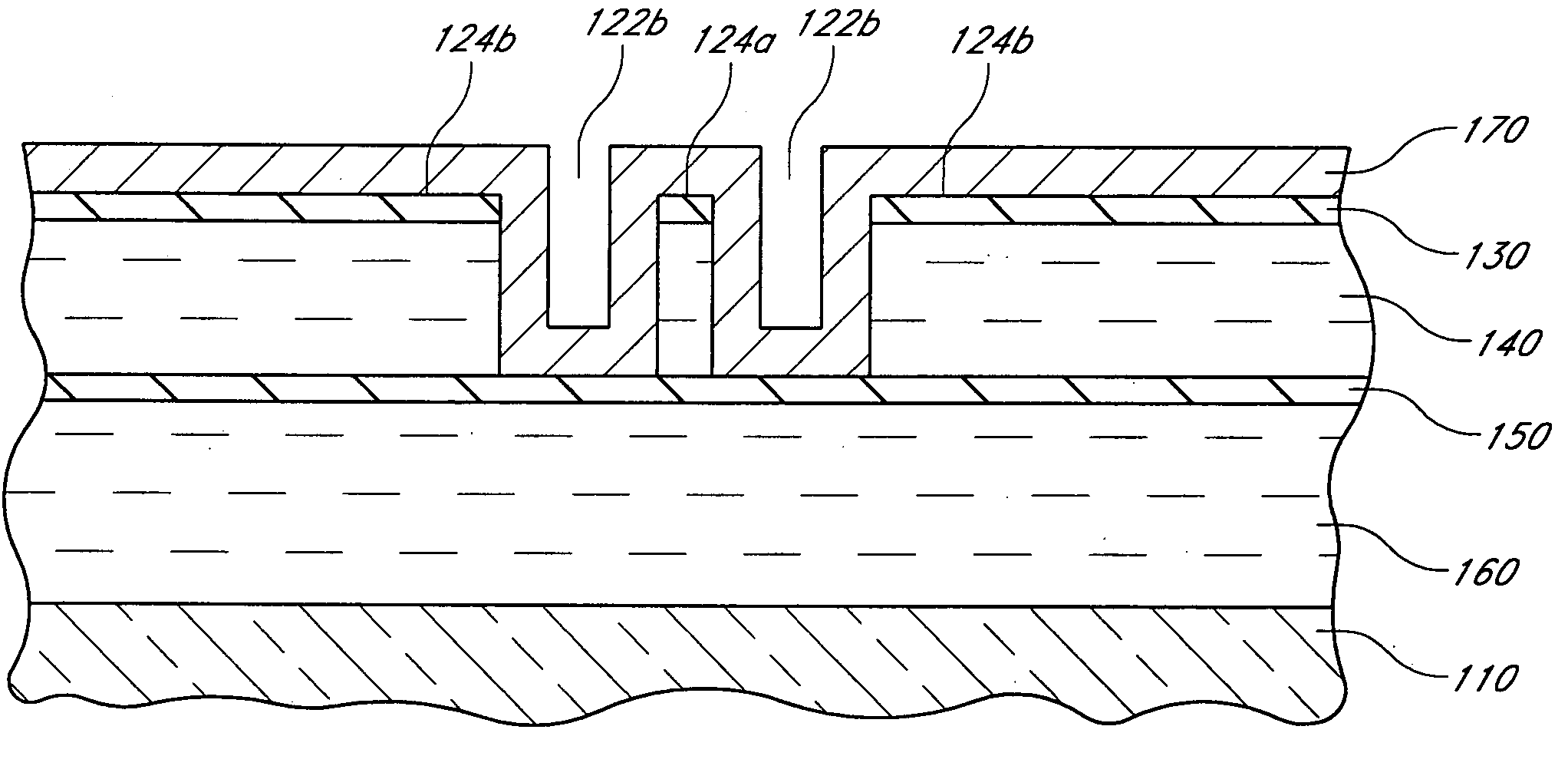
Alignment tolerances between narrow mask lines, for forming interconnects in the array region of an integrated circuit, and wider mask lines, for forming interconnects in the periphery of the integrated circuit, are increased. The narrow mask lines are formed by pitch multiplication and the wider mask lines are formed by photolithography. The wider mask lines and are aligned so that one side of those lines is flush with or inset from a corresponding side of the narrow lines. Being wider, the opposite sides of the wider mask lines protrude beyond the corresponding opposite sides of the narrow mask lines. The wider mask lines are formed in negative photoresist having a height less than the height of the narrow mask lines. Advantageously, the narrow mask lines can prevent expansion of the mask lines in one direction, thus increasing alignment tolerances in that direction. In the other direction, use of photolithography and a shadowing effect caused by the relative heights of the photoresist and the narrow mask lines causes the wider mask lines to be formed with a rounded corner, thus increasing alignment tolerances in that direction by increasing the distance to a neighboring narrow mask line.

Description

REFERENCE TO RELATED APPLICATIONS [0001] This application is related to the following: U.S. patent application Ser. No. ______ to Abatchev et al., filed Aug. 31, 2004, entitled Critical Dimension Control, Attorney Docket No. MICRON.286A (Micron Ref. No. 03-1348.00 / US); U.S. patent application Ser. No. ______ to Abatchev et al., filed Sep. 1, 2004, entitled Mask Material Conversion, Attorney Docket No. MICRON.293A (Micron Ref. No. 03-1435.00 / US); U.S. patent application Ser. No. ______ to Abatchev et al., filed Sep. 2, 2004, entitled Method for Integrated Circuit Fabrication Using Pitch Multiplication, Attorney Docket No. MICRON.294A (Micron Ref. No. 03-1446.00 / US); and U.S. patent application Ser. No. ______ to Tran et al., filed Aug. 31, 2004, entitled Methods for Increasing Photo-Alignment Margins, Attorney Docket No. MICRON.295A (Micron Ref. No. 04-0068.00 / US).BACKGROUND OF THE INVENTION [0002] 1. Field of the Invention [0003] This invention relates generally to integrated circui...

Claims


Application Information

Patent Timeline
Patent Type & Authority Applications(United States)
IPC IPC(8): G03F7/00
CPCH01L21/0337H01L21/0338H01L21/32139H01L21/76838H01L27/10894H01L23/50H01L2924/0002Y10S438/975Y10S438/95H01L27/1052H01L2924/00H10B12/09
Inventor SANDHU, GURTEJ S.CHANCE, RANDAL W.RERICHA, WILLIAM T.
Owner MICRON TECH INC
Why Eureka
Eureka Blog
Learn More