
Double-Shell Core Lithium Nickel Manganese Cobalt Oxides

a cobalt oxide and nickel manganese technology, applied in the field of lithium nickel manganese cobalt oxides, can solve the problems of increasing the cost of this material, different limitations or challenges, and difficult preparation

Active Publication Date: 2012-10-25
UMICORE AG & CO KG +1
View PDF7 Cites 34 Cited by
  • Summary
  • Abstract
  • Description
  • Claims
  • Application Information

AI Technical Summary

Benefits of technology

[0021]In a particular embodiment the first inner layer consists of a LiF film with a thickness of at least 0.5 nm. or at least 0.8 nm, or even at least 1 nm. In another particular embodiment, the fluorine-containing polymer is either one of PVDF, PVDF-HFP or PTFE. The fluorine-containing polymer can be composed of agglomerated primary particles having an average particle size of between 0.2 and 0.5 μm. It is believed that such a particle size is advantageous for the wetting properties of the molten fluorine-containing polymer.

Problems solved by technology

In these substitute materials, depending on the choice of metal composition, different limitations occur or challenges need to be solved.
It has a high capacity, however it is difficult to prepare, since typically a carbon dioxide free atmosphere (oxygen) is needed and special carbonate free precursors like lithium hydroxide are used instead of lithium carbonate.
Hence such manufacturing restraints tend to increase the cost of this material considerably.
It is not fully stable in air, which makes large scale battery production more difficult, and—caused by its lower thermodynamic stability—in real batteries it is responsible for a poor safety record.
Finally, it is very difficult to produce lithium nickel oxide with a low content of soluble base.
The presence of “soluble base” is a disadvantage because a high base content is often connected with problems during battery manufacturing: during slurry making and coating high base causes a degradation of the slurry (slurry instability, gelation) and high base is also a responsible for poor high temperature properties, like excessive gas generation (swelling of the batteries) during high temperature exposure.
Their main drawback is a relatively low reversible capacity.
A further drawback of LMNCO compared with LNO is the relatively low crystallographic density, so the volumetric capacity is also less; and a relatively low electronic conductivity.
Generally, the base content increases, and the safety performance tends to deteriorate with increasing Ni:Mn ratio.
These processes are very bad for battery making.
Li2CO3 and moisture are known to cause severe swelling, and to deteriorate the slurry stability.
Thus the total cost of the process is high.
Evidently, in-situ coating is only efficient if the coating phase wets the core.
However, due to the high melting point of LiF and also due to poor wetting properties, it is not possible to obtain a thin and dense LiF film.
On the other hand, problems arise from poor electronic conductivity, and sometimes the poor transport of lithium across the polymer.
There cannot be found any experimental data in the prior art that would show that the above described approaches are effective to improve the cited problems of LNO and LNMO materials.

Method used


Image

  • Double-Shell Core Lithium Nickel Manganese Cobalt Oxides
  • Double-Shell Core Lithium Nickel Manganese Cobalt Oxides
  • Double-Shell Core Lithium Nickel Manganese Cobalt Oxides

Examples


example 1

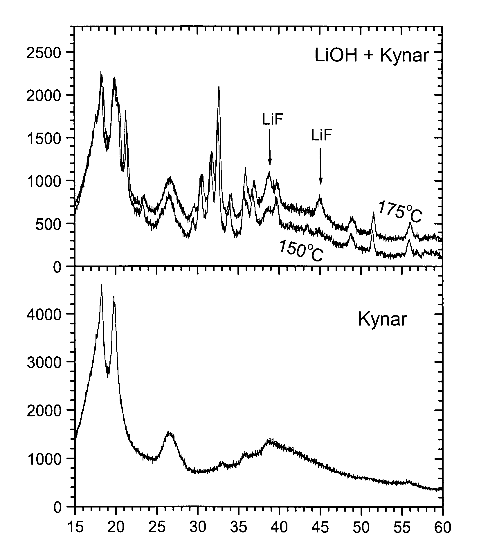
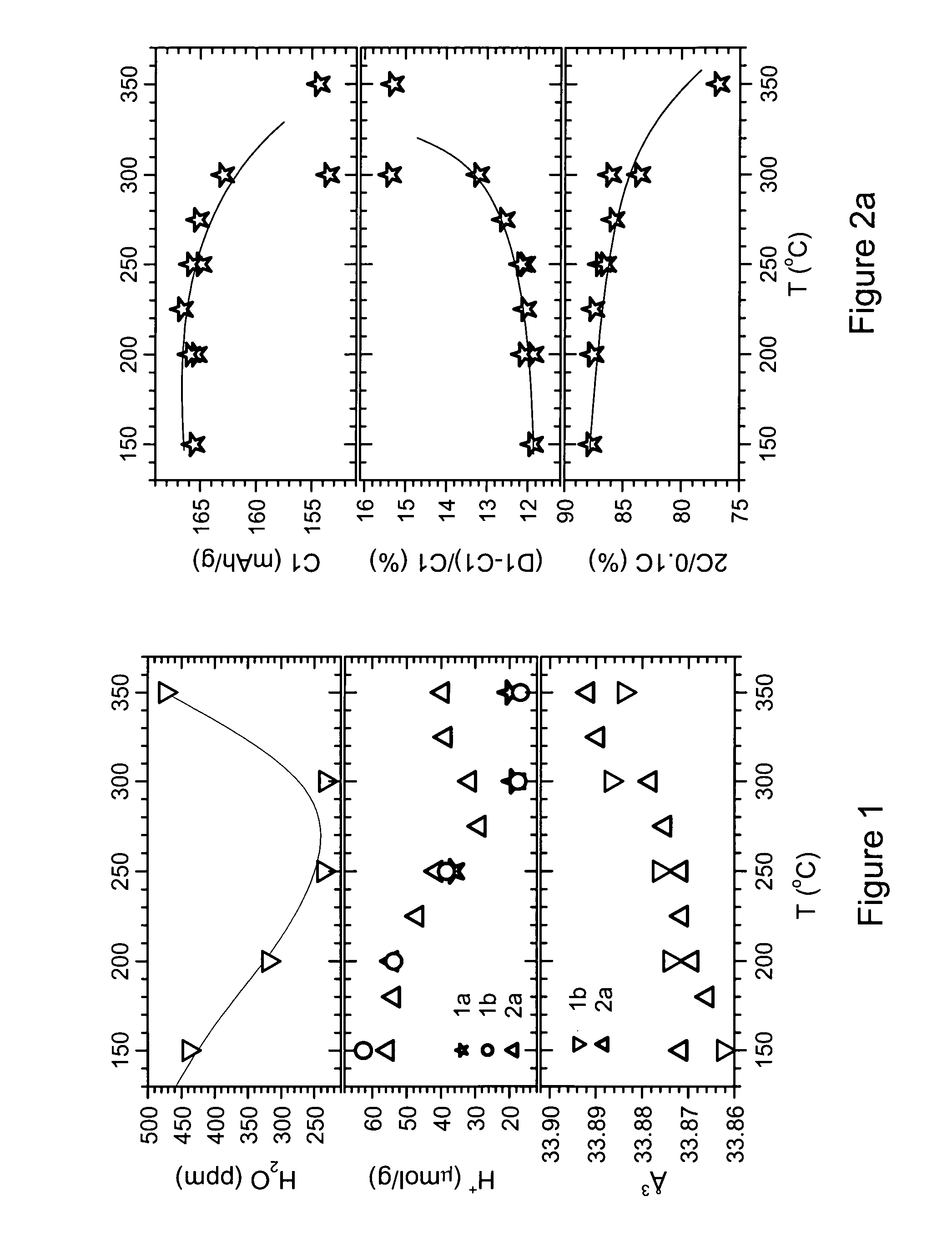
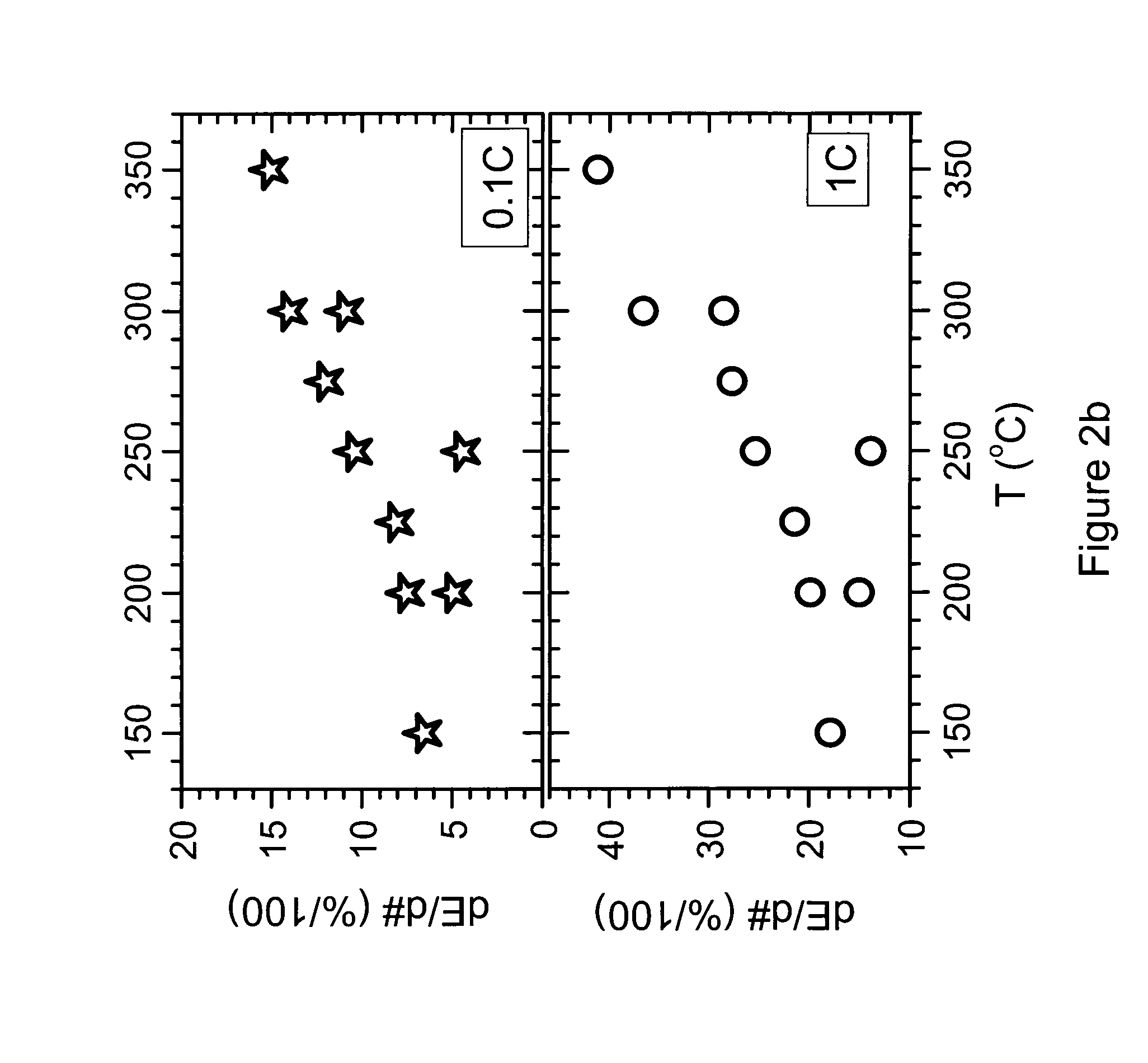
[0074]This example demonstrates the effects of a coating with a fluorine containing polymer followed by a temperature treatment:[0075]1) A reaction between cathode and polymer happening at higher temperature, and[0076]2) Formation of a LiF protective film

[0077]Also, the example investigates the influence of the temperature on samples coated by polymer having a LiF interface. This example shows results for samples prepared by adding 1% polymer. A LNMO mass production sample is used as cathode precursor (precursor=uncoated or bare sample). The composition is Li1+xM1−xO2 with M=Ni0.5M Mn0.3Co0.2 and x about 0.00. The precursor further contains 0.145 mol % 5 and 142 ppm Ca.

[0078]100 g of cathode precursor and 10 g of PVDF powder are carefully premixed using a coffee grinder. Then the 110 g of intermediate mixture is mixed with 900 g remaining cathode precursor, at medium energy using a Haensel type mixer. The precursor-PVDF mixture is sampled to batches of 100 g each. These batches are ...

example 2

[0106]Example 1 investigated a coating by 1% PVDF. However, at treatment temperatures T>275° C., and especially >300° C., it is observed that the decomposing polymer extracts so much Li from the cathode, causing a decrease of the reversible capacity. This indicates that the resulting LiF film might become unnecessarily thick. Therefore the present example illustrates the invention for a heat treatment using less polymer, only 0.3 wt % PVDF. As before, the example investigates the influence of temperature on the preparation of samples coated by polymer having an LiF interface. An LNMO mass production sample is used as cathode precursor. Its composition is Li1+xM1-xO2 with M=Ni0.5Mn0.3Co0.2 and x about 0.00. The precursor further contains 0.145 mol % 5 and 142 ppm Ca.

[0107]100 g of cathode precursor and 3 g of PVDF powder are carefully premixed using a coffee grinder. Then the 103 g of mixture is mixed with the remaining 900 g cathode precursor, and mixed at medium energy using a Haen...

example 3

[0110]This example investigates the influence of temperature on the preparation of LiCoO2 samples coated by polymer having a LW interface. The example discusses the voltage profile and microstructure of a suitable LiCoO2 to give further evidence for the conclusions of examples 1-2. The key conclusions are similar to examples 1-2: between 200-350° C. a LiF film forms. The thickness increases with temperature. Otherwise, a LiF film cannot be retained at higher temperature.

[0111]The example shows results for samples prepared by adding 1% PVDF polymer. A lithium cobalt oxide mass production sample is used as cathode precursor. Its composition is 1 mol % Mg doped LiCoO2, having a mean particles size of 17 μm. 1000 g of this precursor powder and 10 g of PVDF powder are carefully mixed using a Hensel type mixer. The mixture is sampled to batches of 150 g each. These batches are heat treated for 9 h at temperatures ranging from 150-600° C. The resulting powder is sieved. The powders are ana...


PUM

PropertyMeasurementUnit
particle sizeaaaaaaaaaa
thicknessaaaaaaaaaa
thicknessaaaaaaaaaa

Abstract

A lithium transition metal oxide powder for use in a rechargeable battery is disclosed, where the surface of the primary particles of said powder is coated with a first inner and a second outer layer, the second outer layer comprising a fluorine-containing polymer, and the first inner layer consisting of a reaction product of the fluorine-containing polymer and the primary particle surface. An example of this reaction product is LiF, where the lithium originates from the primary particles surface. Also as an example, the fluorine-containing polymer is either one of PVDF, PVDF-HFP or PTFE. Examples of the lithium transition metal oxide are either one of —LiCOdMeO2, wherein M is either one or both of Mg and Ti, with e<0.02 and d+e=1; —Li+aM′1−aO2±bM1kSm with −0.03≦a≦0.06, b<0.02, M′ being a transition metal compound, consisting of at least 95% of either one or more elements of the group Ni, Mn, Co, Mg and Ti; M1 consisting of either one or more elements of the group Ca, Sr, Y, La, Ce and Zr, with 0≦k≦0.1 in wt %; and 0≦m≦0.6, m being expressed in mol %; and —LiaNixCOyM″O2+eAf, with 0.9<a′<1.1, 03.5≦x≦0.9, 0<y≦0.4, 0<z≦0.35, e<0.02, 0≦f≦0.05 and 0.9<(x+y+z+f)<1.1; M″ consisting of either one or more elements from the group Al, Mg, and Ti; A consisting 1000 of either one or both of S and C. For making the coated powder, an example process comprises the steps of:—providing a bare lithium transition metal oxide powder, mixing this powder with a fluorine-containing polymer, and heating the obtained powder-polymer mixture at a temperature between at least 50° C. and at most 140° C. above the melting temperature of the fluorine-containing polymer.

Description

TECHNICAL FIELD AND BACKGROUND[0001]The invention relates to cathode material for rechargeable lithium batteries, particularly lithium nickel manganese cobalt oxides being coated with a fluorine containing polymer and heat treated afterwards.[0002]Previously LiCoO2 was the most used cathode material for rechargeable lithium batteries. However, recently a substitution of LiCoO2 by lithium nickel oxide based cathodes and by lithium nickel manganese cobalt oxides is in full progress. In these substitute materials, depending on the choice of metal composition, different limitations occur or challenges need to be solved. For simplicity reasons, the term “Lithium nickel oxide based cathodes” will be further referred to as “LNO”, and “lithium nickel manganese cobalt oxides” will be further referred to as “LMNCO”.[0003]One example of an LNO material is LiNi0.80Co0.15Al0.05O2. It has a high capacity, however it is difficult to prepare, since typically a carbon dioxide free atmosphere (oxygen...

Claims


Application Information

Patent Timeline
Patent Type & Authority Applications(United States)
IPC IPC(8): H01M4/62H01M4/1395H01M4/131
CPCH01M4/131H01M4/1391H01M4/366Y02E60/122H01M4/62H01M4/623H01M10/052H01M4/525Y02E60/10H01M4/505H01M4/60H01M4/1315H01M4/13915
Inventor PAULSEN, JENSDE PALMA, RANDYHONG, HEONPYOKIM, KYUBO
Owner UMICORE AG & CO KG
Learn More