Eureka AIR delivers breakthrough ideas for toughest innovation challenges, trusted by R&D personnel around the world.

Superbrasvie Tools Containing Uniformly Leveled Superabrasive Particles and Associated Methods

a technology of superabrasives and superabrasives, which is applied in the direction of manufacturing tools, abrasive surface conditioning devices, other chemical processes, etc., can solve the problems of economic infeasibility, reduce costs, and not uniform distribution of diamond or cubic boron nitride particles in abrasives, so as to optimize the performance of the superabrasive tool

Inactive Publication Date: 2011-12-01
KINIK
View PDF2 Cites 18 Cited by
  • Summary
  • Abstract
  • Description
  • Claims
  • Application Information

AI Technical Summary

Benefits of technology

[0015]It is an object of the present invention to provide a method for forming metal bond superabrasive tools, wherein the distribution of the superabrasive grit is monitored to provide improved cutting, sawing, or grinding, characteristics without requiring an increase in the amount of superabrasive grit used to form the tool.
[0016]It is another object of the invention to provide such a method wherein the distribution of the superabrasive grit is controlled to promote more even wear of the tool surface, and thereby lengthen the useful life of the tool.
[0017]It is yet another object of the present invention to provide tools with the minimal amount of superabrasive required to perform the task for which the tool is designed, thereby reducing the cost of making the tool.
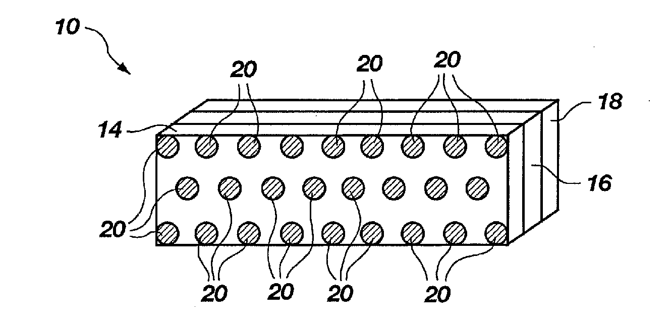
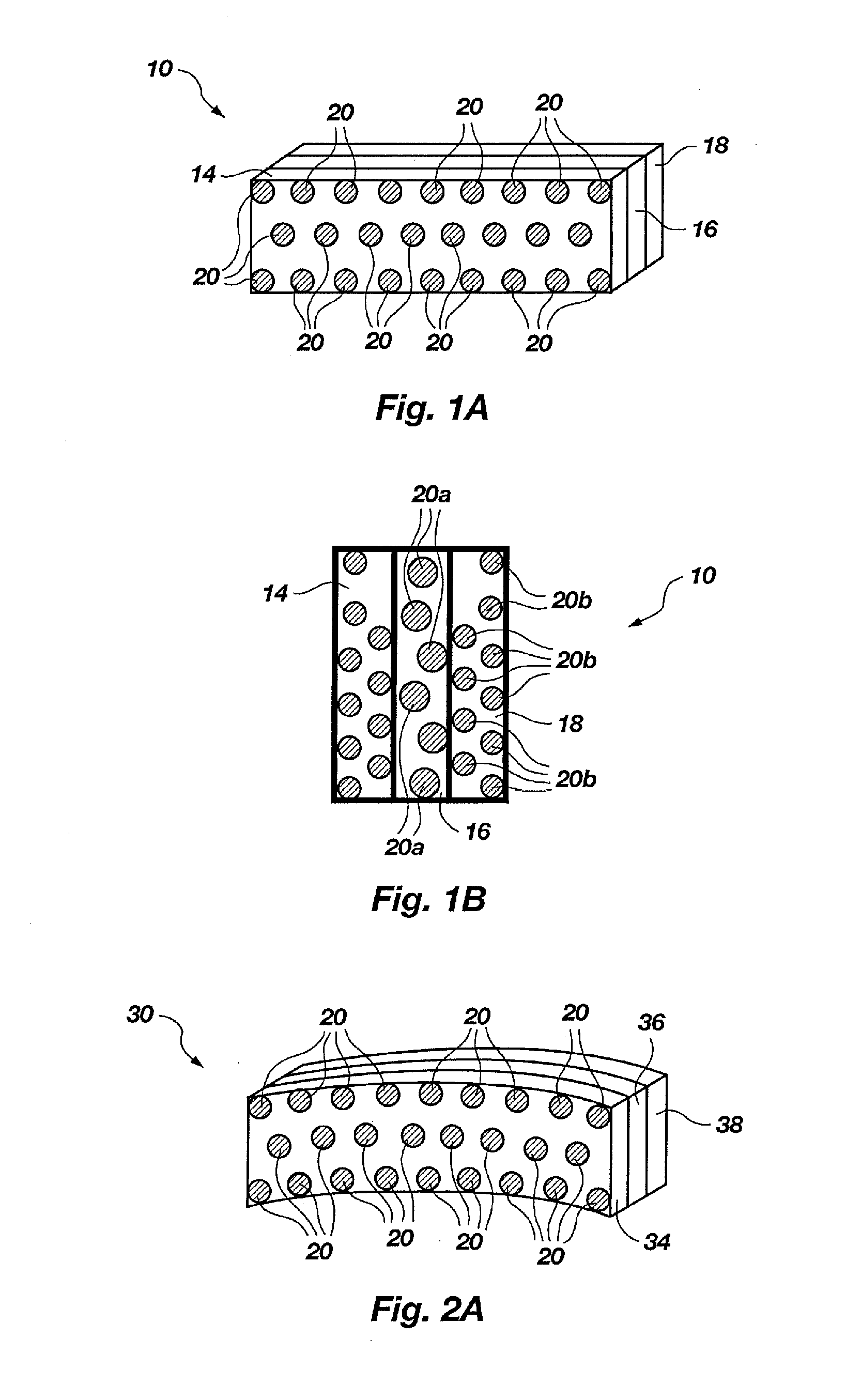
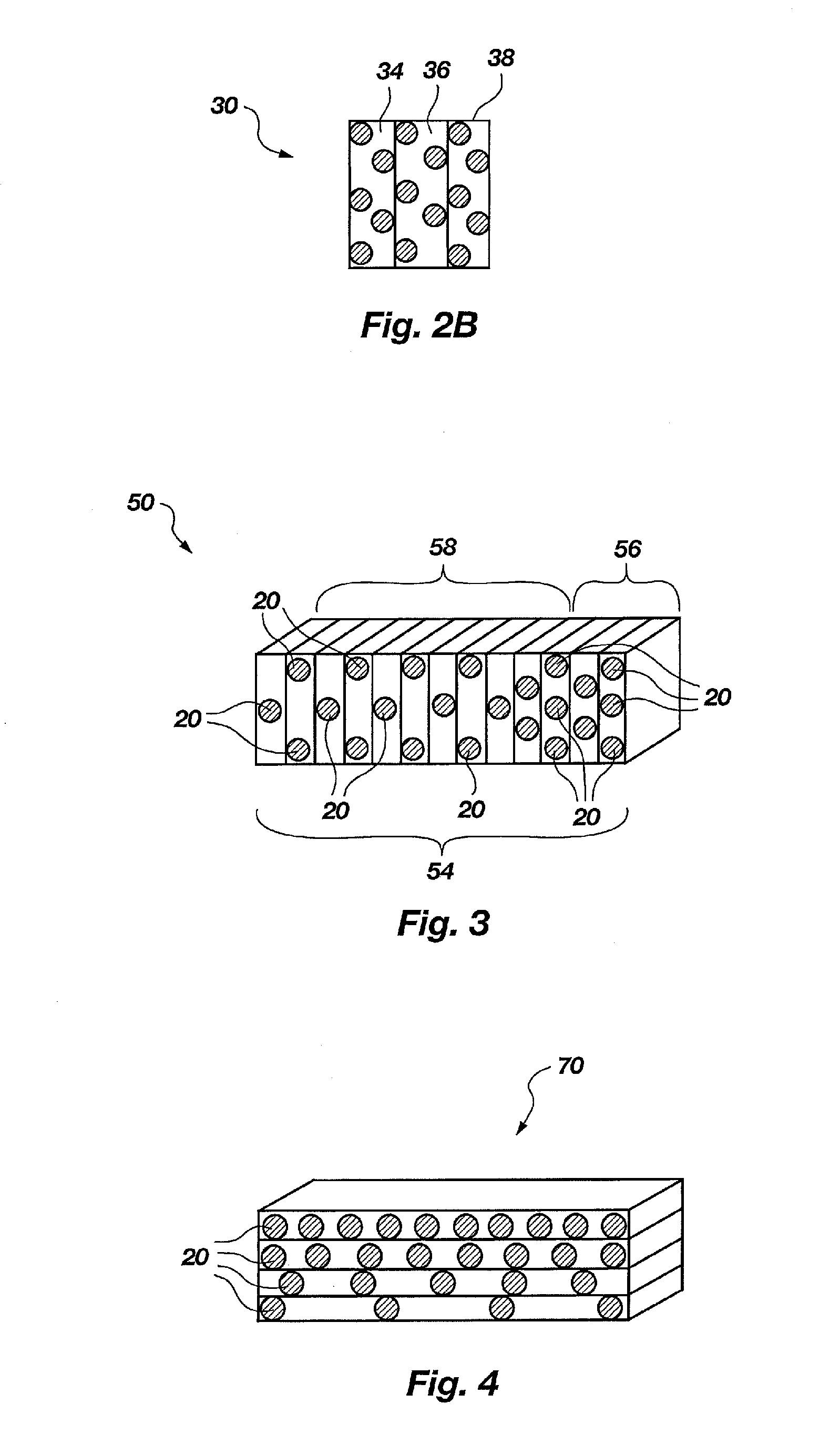
[0018]The above and other objects of the invention are achieved by providing metal bond superabrasive tools wherein the superabrasives, such as diamond or CBN grits, are distributed in a metal matrix in a uniform or a predetermined pattern. While the process of distributing diamond or cubic boron nitride grits in a metal matrix has always been viewed as a complex one and needs to be improved, the present invention provides such an improved process that is easy to manipulate and control, and which can be repeated with a high degree of accuracy. More specifically, the desire distribution of superabrasive particles in a metal matrix body is achieved by assembling layers of metal matrix material that contain a controlled, predetermined pattern of superabrasive particles. Each layer is formed by distributing the superabrasive grit into a layer of bonding metal matrix in a predetermined pattern. Each layer, which is assembled to form a superabrasive impregnated segment, can be of the same distribution pattern and concentration, or the distribution pattern and / or concentration may vary from layer to layer.
[0020]By assembling layers of metal matrix impregnated with superabrasives in a predetermined pattern and concentration into a three dimensional body, the present invention not only provides the desirable diamond / CBN distribution pattern in the tool body, but also provides the flexibility for possible manipulation of diamond concentration at different parts of the same tool body. Thus, for example, diamond particles can be disposed in denser concentrations in some layers than others, and the layers with the greater diamond / CBN concentrations can be disposed within the three-dimensional structure created in such a manner as to prevent the uneven wear patterns that are typical in many prior art diamond tools.
[0022]In accordance with another aspect of the present invention, the pattern in which the superabrasive grit is disposed may be uniform, or may be calculated to provide superabrasive members with particular cutting or sawing abilities. For example, the superabrasive particles may be disposed in varied concentrations to compensate for uneven wear patterns. Thus, the diamond or CBN distribution for the cutting edge of a saw may have a greater distribution of diamond or CBN particles in the lead edge and sides than in the middle portion which is generally subjected to less wear. Likewise, the sizes of the superabrasive particles can be controlled to provide a cutting, grinding, etc., surface which is tailored to the particular uses and wear patterns for the tool.

Problems solved by technology

If superabrasives were not used, many such industries would be economically infeasible.
Despite the tremendous improvements which diamond and cubic boron nitride have provided for cutting, drilling and grinding tools, there are still several disadvantages which, if overcome, would greatly improve performance of the tools, and / or reduce their cost.
For example, the abrasive diamond or cubic boron nitride particles are not distributed uniformly in the matrix that holds them in place.
As a result, the abrasive particles are not positioned to maximize efficiency for cutting, drilling, etc.
Improper spacing of the diamond or CBN abrasive particles typically leads to premature failure of the abrasive surface or structure.
Thus, if the diamond / CBN abrasive particles are too close to one another, some of the particles are redundant and provide little or no assistance in cutting or grinding.
In addition, excess particles add to the expense of production due the high cost of diamond and cubic boron nitride.
Moreover, these non-performing diamond or CBN particles can block the passage of debris, thereby reducing the cutting efficiency.
Thus, having abrasive particles disposed too close to one another adds to the cost, while decreasing the useful life of the tool.
On the other hand, if abrasive particles are separated too far, the work load (e.g., the impact force exerted by the work piece) for each particle becomes excessive.
The damaged or missing abrasive particles are unable to fully assist in the work load.
The failure of each abrasive particle causes a chain reaction which soon renders the tool ineffective to cut, drill, grind, etc.
Because diamond or cubic boron nitride is much larger than the matrix powder (300 times in the above example for making saw segments), and it is much lighter than the latter (about ⅓ in density for making saw segments), it is very difficult to mix the two to achieve uniformity.
Moreover, even when the mixing is thorough, diamond particles can still segregate from metal powder in the subsequent treatments such as pouring the mixture into a mold, or when the mixture is subjected to vibration.
The distribution problem is particularly troublesome for making diamond tools when diamond is mixed in the metal matrix.
Unfortunately, none of the attempted methods have proven effective and, as of today, the distribution of diamond or CBN particles in superabrasive tools is still random and irregular, except for some special cases such as for drillers or dressers, where large diamond particles are individually set by hand in the surface to provide a single layer.
Although the above-described coating metal has certain merit, in practice, uniformity of coating is very difficult to achieve.
There is yet another limitation associated with the current methods of coating diamond grits.
For example, saw segments tend to wear faster on the edge or front than the middle.
These higher concentration (known as “sandwich” segments) are difficult to fabricate by mixing coated diamond with metal powder to achieve a controlled distribution of the diamond particles in the segment.
Thus, despite the known advantages of having varied diamond grit sizes and concentration levels, such configurations are seldom used because of the lack of a practical method of making thereof.
In summary, current arts are incapable of efficiently controlling the uniformity of diamond or CBN distribution in cutting tools.
Likewise, the current methods are inadequate to provide effective control of size variations and / or concentration variations on different parts of the same tool.
Moreover, even when the distribution is made relatively uniform, current arts cannot tailor the pattern of the distribution to overcome or compensate for typical wear patterns for the abrasive material, when used for a particular purpose.
As a result, the superabrasive tool will cut faster and its working life will be extended for a considerable amount of time.

Method used


Image

  • Superbrasvie Tools Containing Uniformly Leveled Superabrasive Particles and Associated Methods
  • Superbrasvie Tools Containing Uniformly Leveled Superabrasive Particles and Associated Methods
  • Superbrasvie Tools Containing Uniformly Leveled Superabrasive Particles and Associated Methods

Examples


example 1

[0072]40 / 50 mesh diamond grit (SDA-85 made by De Beers Company) were mixed with metal powder to form a mixture with a diamond concentration of 20 (5% of total volume). Five different proportions of cobalt (about 1.5 micrometer in size) and bronze (about 20 micrometers in size) were used for the matrix powder. An acrylic binder was added (8% by weight) to the mixture and the charge was blended to form a cake. The cake was then rolled between two stainless steel rollers to form sheets with a thickness of 1 mm. These sheets were cut in the shape of saw segments with a length of 40 mm and width of 15 mm. Three each of such segments were assembled and placed into a typical graphite mold for making conventional diamond saw segments. The assembled segments were pressed and heated by passing electric current through the graphite mold. After sintering for three minutes, the segments were consolidated to a height of 9 mm with less then 1% porosity. Twenty-four segments for each composition we...

example 2

[0073]The same procedures were followed as Example 1, but with 8 thinner layers (0.4 mm) being used to form each segment. The diamond concentration was reduced to 15 and particles were planted according to the illustration as shown in FIGS. 5A through 5D, for each layer. The diamond distribution was much improved. As a result, the performance of these blades were equal or better than those made by conventional methods with diamond concentration of 20.

example 3

[0074]Iron powders of about 100 mesh were mixed with an S-binder made by Wall Colmonoy Company to form a cake. The cake was then rolled to form sheets of 0.4 mm in thickness. 40 / 50 mesh SDA-100 diamond grit was planted into these sheets to attain a concentration of 15. These diamond containing sheets were cut in the shape of saw segments with a length of 40 mm and width of 9 mm. Eight of such segments were assembled as a group and placed in a graphite mold. Twenty-four groups were placed horizontally, and another twenty-four groups were placed vertically in the graphite mold. Nicrobraz LM powder (−140 mesh) (made by Wall Colmonoy Company) was added on the top of these segments. These samples were heated in a vacuum furnace (10−5 torr) to 1050° C. for 20 minutes for horizontally placed segments, and 30 minutes for vertically placed segments. The melted LM alloy (Ni—C—B—Si with a liquidus point at 1000° C.) infiltrated into these segments and filled the porosity. The excess LM braze o...


PUM


Abstract

A superabrasive tools having uniformly leveled superabrasive particles and associated methods are provided. In one aspect, for example, a superabrasive can include a metal matrix configured for bonding superabrasive particles and a plurality superabrasive particles held in the metal matrix at specific positions according to a predetermined pattern, wherein tips of each of the plurality of the superabrasive particles protrude from the metal matrix to a uniform height.

Description

PRIORITY DATA[0001]This application is a continuation of U.S. patent application Ser. No. 12 / 463,897, filed on May 11, 2009, which is a continuation of U.S. patent application Ser. No. 11 / 818,894, filed on Jun. 14, 2007, which is a continuation of U.S. patent application Ser. No. 10 / 791,300, filed Mar. 1, 2004, now issued as U.S. Pat. No. 7,323,049, which is a continuation-in-part of U.S. patent application Ser. No. 10 / 259,168, filed Sep. 27, 2002, now issued as U.S. Pat. No. 7,124,753, which is a continuation-in-part of U.S. patent application Ser. No. 09 / 935,204, filed Aug. 22, 2001, now issued as U.S. Pat. No. 6,679,243, and of U.S. patent application Ser. No. 10 / 109,531, filed Mar. 27, 2002, now issued as U.S. Pat. No. 6,884,155. U.S. Pat. No. 6,679,243 is a continuation-in-part of U.S. patent application Ser. No. 08 / 835,117, filed on Apr. 4, 1997 and a continuation-in-part of U.S. patent application Ser. No. 09 / 399,573, filed Sep. 20, 1999, now issued as U.S. Pat. No. 6,286,498...

Claims


Application Information

Patent Timeline
IPC IPC(8): B24D3/06B32B5/16C09K3/14
CPCB01J3/062B01J2203/061B01J2203/062Y10T428/24893B01J2203/0655B01J2203/066B01J2203/068B01J2203/0645B24B53/017B24B53/02B24D3/06B24D11/005
Inventor SUNG, CHIEN-MIN
Owner KINIK
Why Eureka
Eureka Blog
Learn More