Reflective optical element and method for production of such an optical element

a reflective optical element and optical imaging technology, applied in the field of reflective optical elements, can solve the problems of critical disturbance of optical imaging at the corresponding reflective optical element, increase in microroughness and hence surface roughness, and degradation of reflectivity and optical imaging of the reflective optical element, and achieve high reflectivity and reduce stress

Active Publication Date: 2011-09-22
CARL ZEISS SMT GMBH
View PDF18 Cites 11 Cited by
  • Summary
  • Abstract
  • Description
  • Claims
  • Application Information

AI Technical Summary

Benefits of technology

[0008]It is an object of the present invention to provide reflective optical elements for operating wavelengths in the soft X-ray and extreme ultraviolet wavelength range and a method for producing them in which both a stress reduction and a high reflectivity are achieved.SUMMARY OF THE INVENTION
[0013]It has been found that through the coating by high-energy particles, a crystallization can be effectively prevented even in the case of relatively thick layers. Consequently, for the same thickness, it is possible to apply layers which have a lower surface roughness. In the case of stress-reducing multilayer systems, in particular, as a result higher Γ values can be chosen and significantly lower numbers of periods suffice to sufficiently compensate for the stress of an overlying highly reflective multilayer system without having to accept losses in the reflectivity and the optical imaging properties. It may already be sufficient to apply only one stress-compensating layer by high-energy layer-forming particles. As a result, the coating process can be shortened and the probability of failure on account of defective coatings can be reduced.
[0014]The deposition of interlayers with the aid of layer-forming particles having an energy of 40 eV or interlayers that are smoothed with the aid of an ion beam permits existing coating processes to be altered with little outlay in order to provide reflective optical elements which have both low stress and a high reflectivity. In this case, the interlayer can also both be deposited with higher-energy layer-forming particles and be subsequently polished by an ion beam. The smooth or smoothed interlayer has the function of compensating for inhomogeneities in the surface of the underlying stress-reducing multilayer system and of thereby reducing the surface roughness.
[0016]In addition, said object is achieved by a reflective optical element for an operating wavelength in the soft X-ray and extreme ultraviolet wavelength range, in particular for use in an EUV lithography apparatus, which has a multilayer system composed of at least two alternating materials having different real parts of the refractive index at the operating wavelength on a substrate, which exerts a layer stress on the substrate, wherein an amorphous layer of the material having a lower real part of the refractive index at the operating wavelength is arranged between the multilayer system and the substrate, wherein the layer thickness is dimensioned in such a way that the layer stress of the multilayer system is compensated for, wherein the layer has a surface roughness of less than 0.20 nm.

Problems solved by technology

Within multilayer systems, as early as during the coating process a stress can build up which acts on the underlying substrate and deform it to such a great extent that the optical imaging at the corresponding reflective optical element is critically disturbed.
The crystallite sizes increase as the layer thickness increases, which leads to an increase in the microroughness and hence the surface roughness.
Since this roughness also continues in the overlying highly reflective multilayer system, both the reflectivity and the optical imaging of the reflective optical element deteriorate.
However, this entails the disadvantage of a coating process having an increased time duration and hence also a greater risk of failure as a result of incorrect coating.

Method used


Image

  • Reflective optical element and method for production of such an optical element
  • Reflective optical element and method for production of such an optical element
  • Reflective optical element and method for production of such an optical element

Examples


Embodiment Construction

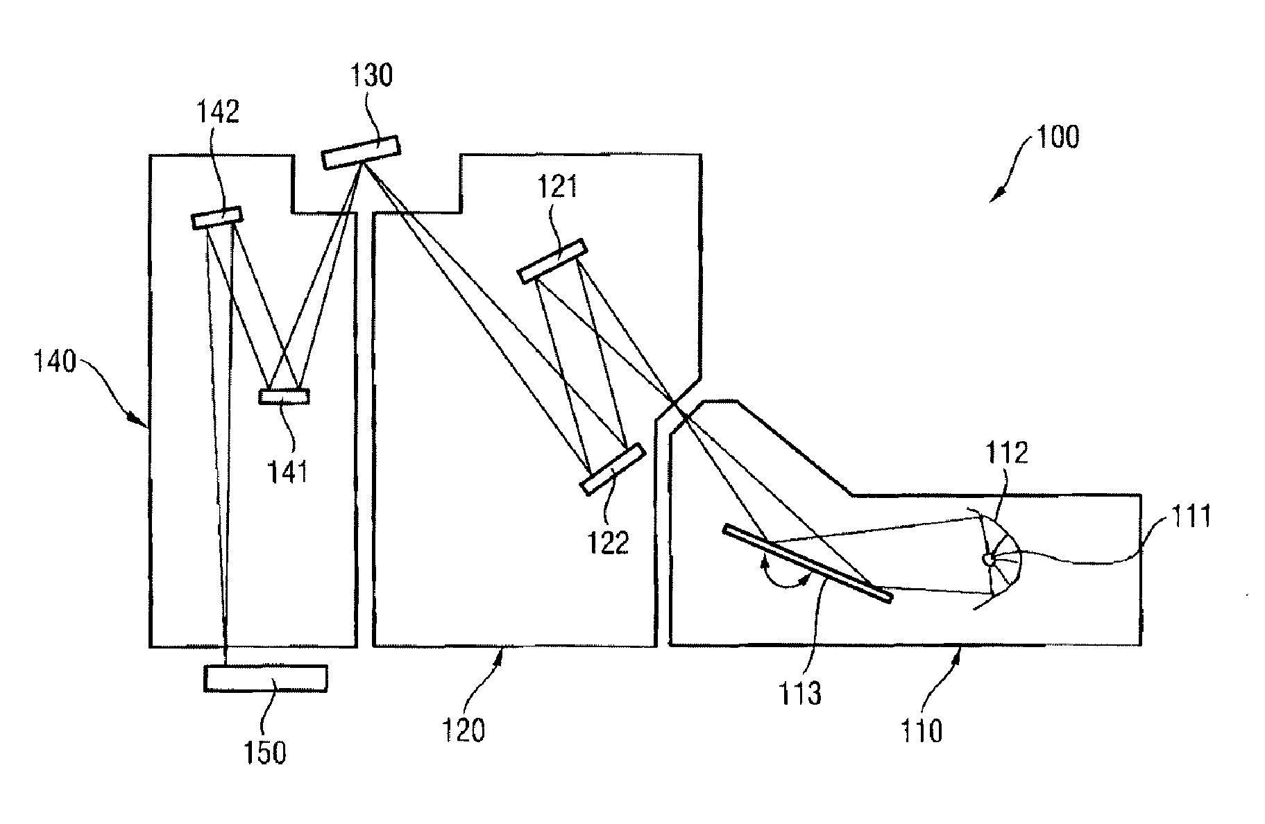
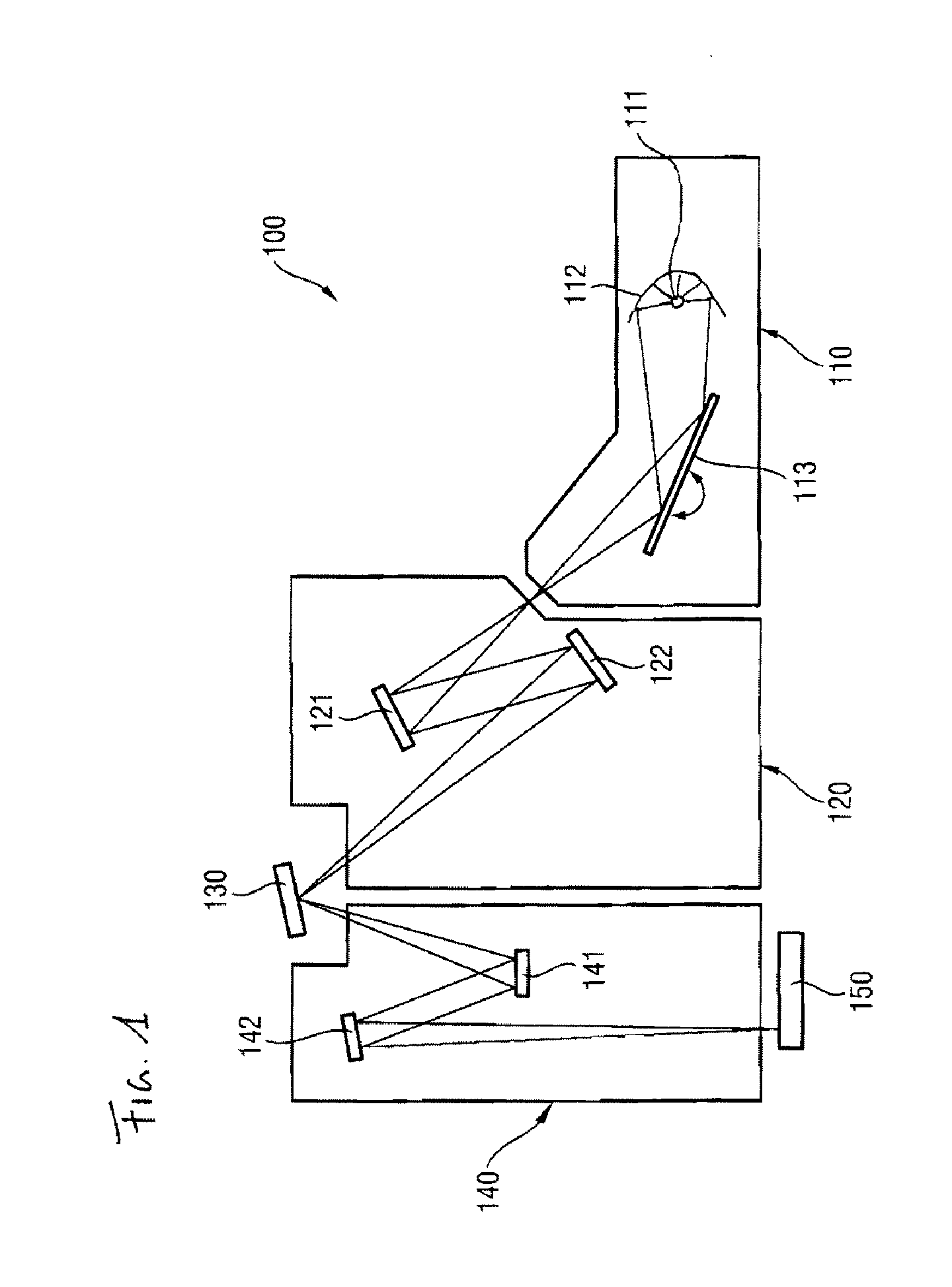
[0027]FIG. 1 schematically illustrates an EUV lithography apparatus 100. Essential components are the beam shaping system 110, the illumination system 120, the photomask 130 and the projection system 140.

[0028]By way of example, a plasma source or else a synchrotron can serve as radiation source 111 for the beam shaping system 110. For the wavelength range of 5 nm to 12 nm, in particular, X-ray lasers (X-FEL) are also appropriate as radiation source. The emerging radiation is firstly concentrated in a collector mirror 112. In addition, the desired operating wavelength is filtered out with the aid of a monochromator 113 by varying the angle of incidence. In the wavelength range mentioned the collector mirror 112 and the monochromator 113 are usually embodied as reflective optical elements which, in order to achieve a reflection of the radiation of the operating wavelength, have a multilayer system composed of at least two alternating materials having different real parts of the refra...


PUM

PropertyMeasurementUnit
energyaaaaaaaaaa
energyaaaaaaaaaa
surface roughnessaaaaaaaaaa

Abstract

In order to produce stress-reduced reflective optical elements (1) for an operating wave length in the soft X-ray and extreme ultraviolet wavelength range, in particular for use in EUV lithography, it is proposed to apply, between substrate (2) and a multilayer system (4) optimized for high reflectivity at the operating wavelength, a stress-reducing multilayer system (6) with the aid of particle-forming particles having an energy of 40 eV or more, preferably 90 eV or more. Resulting reflective optical elements are distinguished by low surface roughness, a low number of periods in the stress-reducing multilayer system and also high Γ values of the stress-reducing multilayer system.

Description

CROSS-REFERENCE TO RELATED PATENT APPLICATIONS[0001]This is a Continuation of International Application PCT / EP2009 / 006112, with an international filing date of Aug. 22, 2009, which was published under PCT Article 21(2) in English, which claims priority under 35 U.S.C. §119(a) to German Patent Application No. 10 2008 042 212.6, filed on Sep. 19, 2008; the present application also claims the benefit under 35 U.S.C. §119(e)(1) of U.S. Provisional Application No. 61 / 098,568, filed on Sep. 19, 2008. The entire contents of the International Application and the priority applications are hereby incorporated into the present application by reference.FIELD OF AND BACKGROUND OF THE INVENTION[0002]The present invention relates to methods for producing a reflective optical element for an operating wavelength in the soft X-ray and extreme ultraviolet wavelength range, in particular for use in an EUV lithography apparatus, which has a multilayer system composed of at least two alternating material...

Claims


Application Information

Patent Timeline
Patent Type & Authority Applications(United States)
IPC IPC(8): G03B21/28F21V9/06F21V7/22G03B27/54B32B37/02B32B37/14
CPCB82Y10/00B82Y40/00G02B5/0891G03F1/24G21K2201/067G03F7/70783G03F7/70941G03F7/70958G21K1/062G03F7/70316G02B5/0875G03F7/20G21K1/06H01L21/027
Inventor VON BLANCKENHAGEN, GISELA
Owner CARL ZEISS SMT GMBH
Why Eureka
Try Eureka