
Translucent material and manufacturing method of the same

a technology of transparent material and manufacturing method, which is applied in the field of transparent material, can solve the problems of inability to fully understand the concept of space filling with polyhedron microparticles, the manufacturing method is vastly different from the hydrothermal synthesis method founded on liquid phase, and the process is extremely complicated and non-productive, so as to achieve effective suppression of gaps in the finished sintered body and promote sintering

Inactive Publication Date: 2009-03-26
FUJIFILM CORP
View PDF13 Cites 18 Cited by
  • Summary
  • Abstract
  • Description
  • Claims
  • Application Information

AI Technical Summary

Benefits of technology

[0029]Specifically, objects of the present invention are to provide a translucent material with a high filled space percentage and superior in transparency with little optical scattering, and to provide a production method for this kind of translucent material.
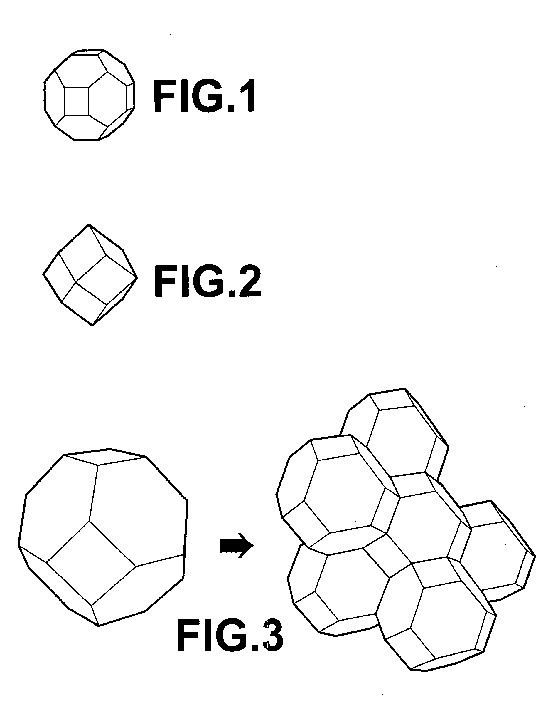
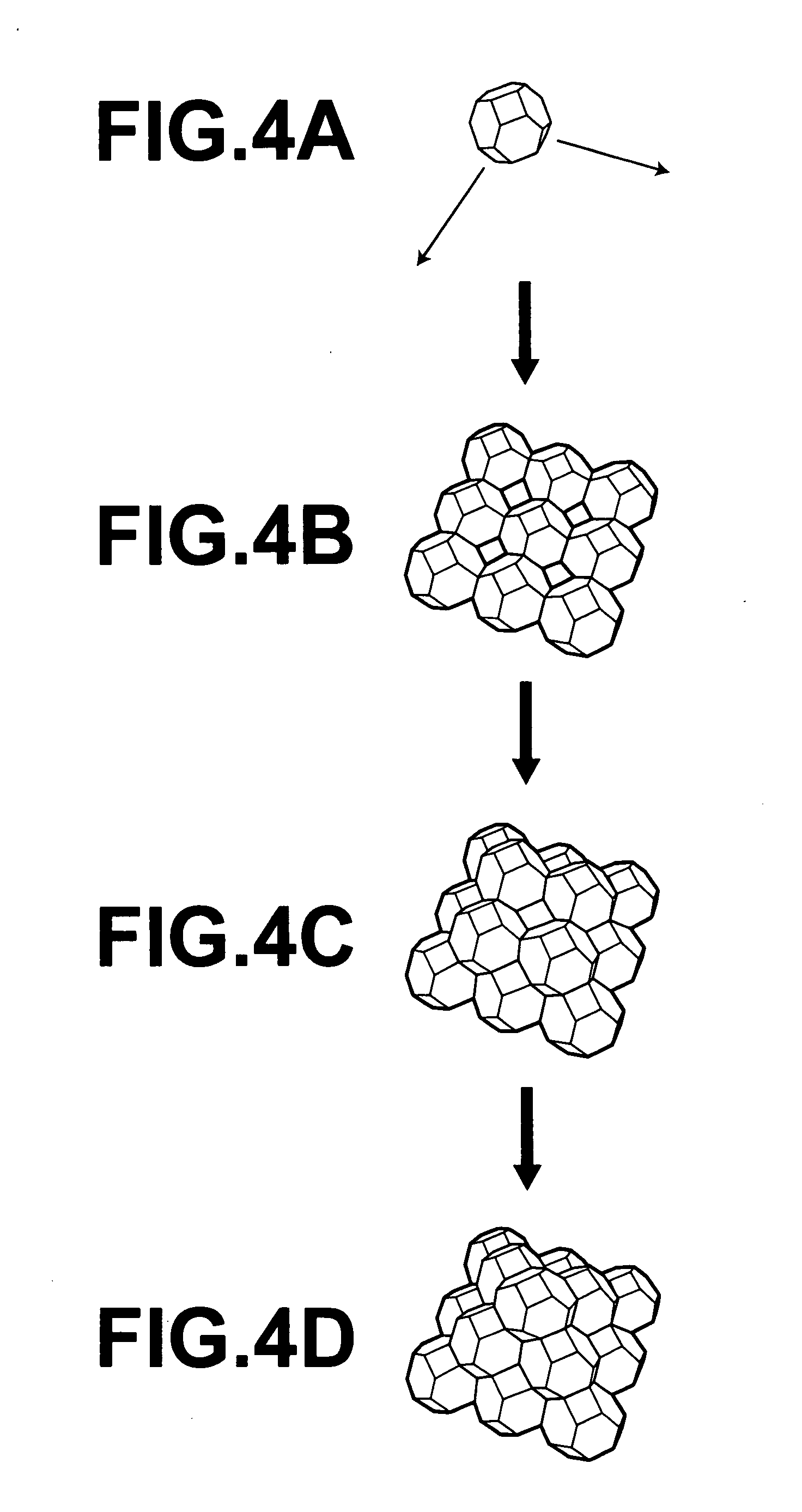
[0045]Because the translucent material of the present invention is a translucent material in which the micro-structure constituting this ceramic sintered body comprises a particle phase consisting of a plurality of particles of a single composition with a monocrystal structure of the same size and the same shape, and a grain boundary phase that is produced at the boundary surfaces where the aforementioned particles contact each other, microparticles of a single composition can be arranged and filled in the space at high density to make a translucent material with superior light transmittance and little optical scattering.
[0050]However, the translucent material manufacturing method of the present invention causes adhesion of amorphous fine particles manufactured by a separate liquid phase synthesis onto the surfaces of particles synthesized by a liquid phase method, and sinters microparticles in a highly reactive state, and therefore, the production of gaps in the finished sintered body can be effectively suppressed, and sintering can be promoted.

Problems solved by technology

Then, there was nothing at all in these articles regarding the concept of space filling with polyhedron microparticles.
In this method, a chloride solution or citric acid solution is spray dried in the first stage, the crystal nucleation density is next adjusted by heating, and then hydrothermal synthesis is conducted in an autoclave, and therefore the process was extremely complicated and non-productive.
Nonetheless, all of these differ from the common method of hydrothermal synthesis, and resemble the flax method in which the substance in solution is heated at 500° C., and then this amorphous body is loaded in an autoclave and processed in the vicinity of 600° C. Consequently, this manufacturing method is vastly different from the hydrothermal synthesis method founded on liquid phase.
139-146, 1996), but with thermal processing at 1200° C. and the like, it would be difficult to say that this is a preferable method in terms of industrial applicability.
Nonetheless, this is special equipment, and problems appear to remain in terms of production characteristics and uniform conditions.
Moreover, although Japanese Unexamined Patent Publication No. 2000-129255 describes a manufacturing method going through hydrothermal processing of terbium-activated indium aluminum oxide luminescent material (including compositions with a garnet structure) applicable to forming uniform and dense high-intensity luminescent films for cathode ray tubes, luminescent lamps, plasma display panels and field emission displays, it is difficult to say that the production characteristics are applicable as a manufacturing method.
However, the luminescent materials claimed in this patent literature are luminescent materials that emit in the visible region by ultraviolet ray excitation, and are fundamentally different than the present invention because these materials are not used in a high-density sintered form, and are limited to used as a powder.
However, the technique of space filling is not described at all in this patent literature.

Method used


Image

  • Translucent material and manufacturing method of the same
  • Translucent material and manufacturing method of the same
  • Translucent material and manufacturing method of the same

Examples


example 1

[0076]17.237 g of yttrium nitrate [Y(NO3)3.6H2O] and 28.133 g of aluminum nitrate [Al(NO3)3.9H2O] respectively were precisely weighed, and dissolved in approximately 40 ml of water in a beaker. Meanwhile, about 20 g of KOH granules were weighed in a separate beaker making a total of about 30 to 40 ml, and this was gradually added while agitating into the aqueous solution containing the yttrium and aluminum. Then, KOH granules were suitably added to make the pH 12.0, and the total amount of solution was brought to 100 ml. This raw material aqueous solution was placed in an autoclave made of Hastelloy, and was allowed to react at 355° C. for 2 hours while agitating in an agitation apparatus that had undergone platinum lining processing.

[0077]After the reaction, the internal solution is moved to a beaker, and a decantation process that eliminates just the supernatant part is conducted 10 or more times with hot water, and finally the reaction precipitate is filtered. Part of this filter...

example 2

[0079]An aqueous solution of equal concentrations of yttrium, aluminum and KOH alkali adjusted in advance for hydrothermal synthesis was used, and was added to fine crystalline particles prepared by the same hydrothermal synthesis as example 1. At this time, the mol ratio of fine crystalline particles and the added aqueous solution (amount of YAG raw material mixed in) converted to YAG was pre-adjusted to about 100:1. The solution prepared in this way was again allowed to react for 1 hour at 250° C. in an autoclave. After removing from the autoclave and conducting decantation 10 times or more, this was made into a mixed solution by mixing together with a dispersion medium in the same way as in example 1, and was poured in a container with a bottom having an extremely smooth finish, and the particles were allowed to slowly settle.

[0080]Next, the supernatant was gently wiped off, and this was allowed to dry undisturbed to make a pancake-shaped substance. A sintered body was obtained b...

example 3

[0081]17.237 g of yttrium nitrate [Y(NO3)3.6H2O] and 28.133 g of aluminum nitrate [Al(NO3)3.9H2O] respectively were precisely weighed, and dissolved in approximately 40 ml of water in a beaker. Meanwhile, about 20 g of KOH granules were weighed in a separate beaker making a total of about 30 to 40 ml, and this was gradually added while agitating into the aqueous solution containing the yttrium and aluminum. Then, KOH granules were suitably added to make the pH 11.5, and the total amount of solution was brought to 100 ml. This raw material aqueous solution was placed in an autoclave made of Hastelloy, and was allowed to react at 300° C. for 30 minutes while agitating in an agitation apparatus that had undergone platinum lining processing.

[0082]After the reaction, the internal solution is moved to a beaker, and a decantation process that eliminates just the supernatant part is conducted 10 or times with hot water, and finally the reaction precipitate is filtered. Part of this filtered...


PUM

PropertyMeasurementUnit
emission wavelength bandaaaaaaaaaa
wavelengthsaaaaaaaaaa
temperatureaaaaaaaaaa

Abstract

After synthesizing particles by liquid phase synthesis, the solution is substituted without drying these particles, and here, a solution comprising a grain boundary phase composition consisting of at least one or more types selected from a group consisting of Al2O3, yttrium oxide, silicon oxide, yttrium-silicon complex oxide, aluminum-silicon complex oxide, and a compound having a garnet structure with a lower melting point than the aforementioned particles, or a solution comprising a precipitate is introduced. Microparticles are adjusted by allowing adhesion and growth of the solution comprising a composition of grain boundary phase or the solution comprising a precipitate on the surface of the particles; these microparticles are allowed to align in 3-dimensions in solution and are formed into a molded body, and this molded body is sintered.

Description

TECHNICAL FIELD[0001]The present invention relates to a translucent material used in ceramic materials that oscillate based on excitation by a semiconductor laser, and light-emitting ceramic materials that adjusts the color tone of a semiconductor light emitting diode based on excitation by light emitted from the semiconductor light emitting diode.BACKGROUND ART[0002]By doping with rare earths, YAG (═Y3Al5O12) becomes a solid laser oscillation material, and although researched extensively, the majority of studies have used monocrystals. Nonetheless, recent findings have revealed that sintered ceramics can impart equivalent characteristics, and therefore research and development worldwide, especially in Japan, is taking up approaches to solid laser materials based on transparent ceramics that have superior cost advantages.[0003]Reviewing the research history, the YAG family first appears when the hydrothermal synthesis of (Y, Tb, Dy, Ho, Yb)3Al5O12 was reported in Russia in 1967. The...

Claims


Application Information

Patent Timeline
Patent Type & Authority Applications(United States)
IPC IPC(8): C01F17/00C04B35/64C04B35/44H01S3/16
CPCC01F17/0025H01L33/502C01P2002/34C01P2002/77C01P2002/84C01P2004/01C01P2004/30C04B35/01C04B35/44C04B35/62813C04B35/62886C04B2235/3222C04B2235/3224C04B2235/3225C04B2235/3227C04B2235/3286C04B2235/443C04B2235/52C04B2235/5481C04B2235/602C04B2235/761C04B2235/763C04B2235/764C04B2235/768C04B2235/85C04B2235/9653C01P2002/30C01F17/34
Inventor SUZUKI, MASAYUKIIKADA, TOMOTAKE
Owner FUJIFILM CORP
Learn More