Seal structure

A sealing structure and structure technology, which is applied to the sealing of engines, electrical equipment structural parts, electrical equipment shells/cabinets/drawers, etc., can solve problems such as inability to eliminate gap c, insufficient countermeasures, etc., and achieve the goal of suppressing the formation of gaps Effect

Active Publication Date: 2014-06-25
NOK CORP
View PDF12 Cites 5 Cited by
  • Summary
  • Abstract
  • Description
  • Claims
  • Application Information

AI Technical Summary

Problems solved by technology

[0006] In addition, as a prior art, it has been proposed to reduce the above-mentioned gap c by providing a sealing protrusion on the thickness surface (side surface or upper surface) of the grommet 54. However, simply providing the sealing protrusion in this way cannot eliminate the gap c. not adequate as a countermeasure

Method used


Image

  • Seal structure
  • Seal structure
  • Seal structure

Examples


Embodiment

[0128] Next, embodiments of the present invention will be described with reference to the drawings.

no. 1 example …

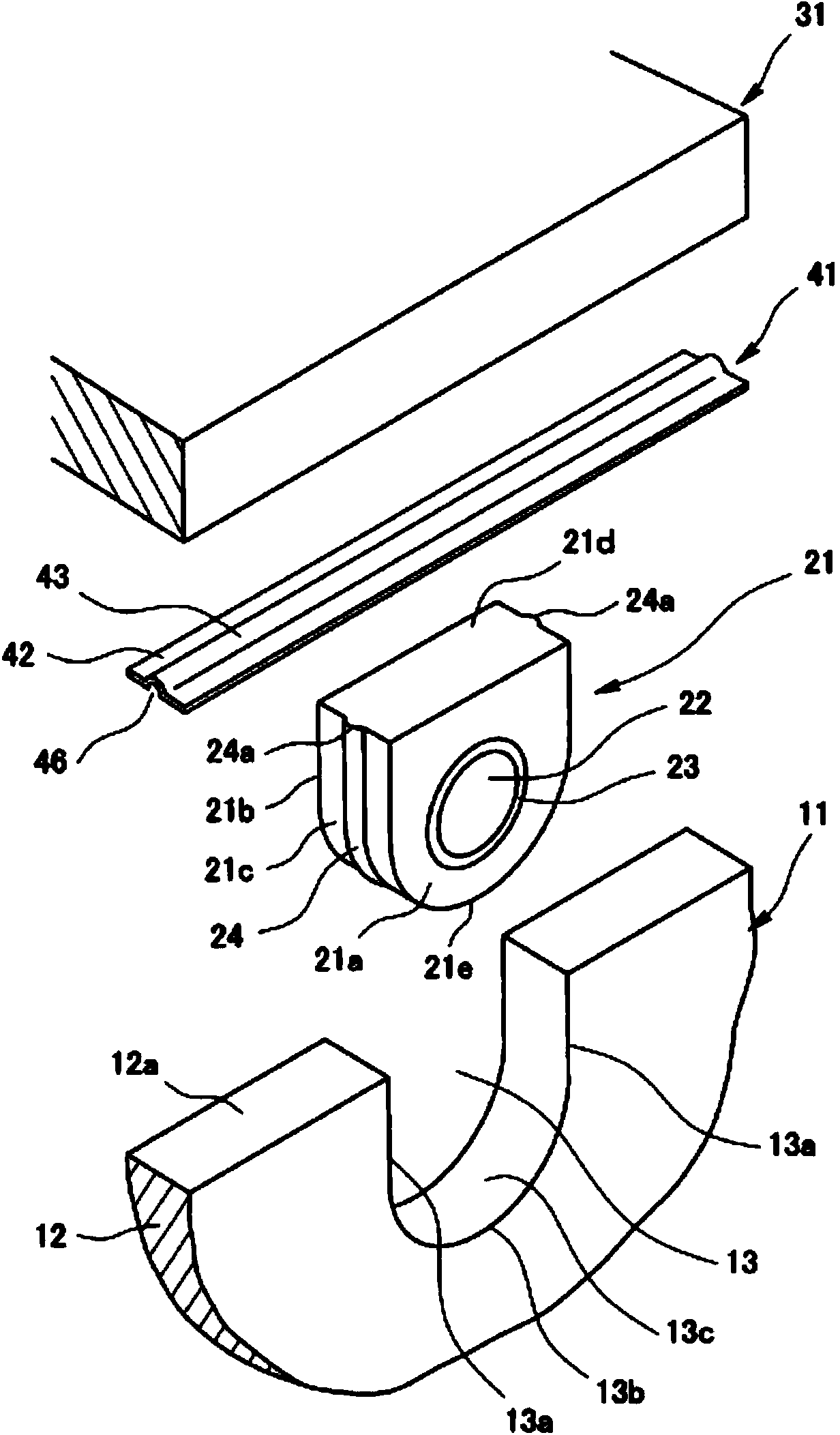
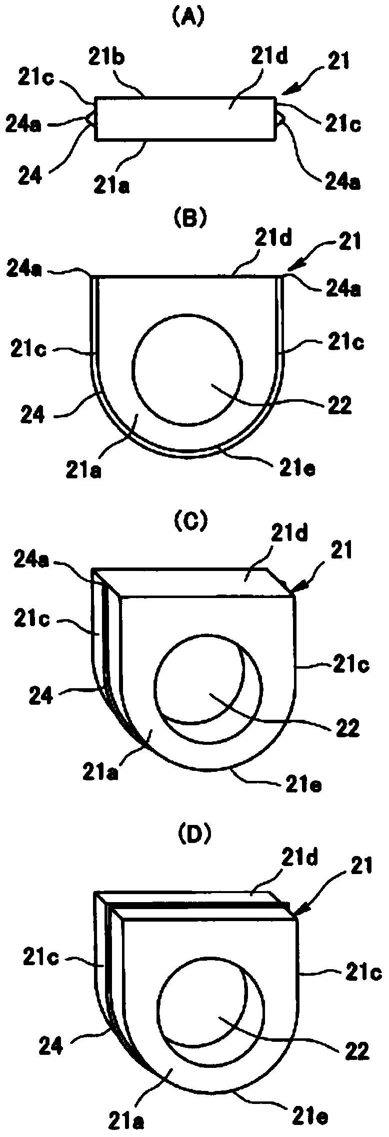
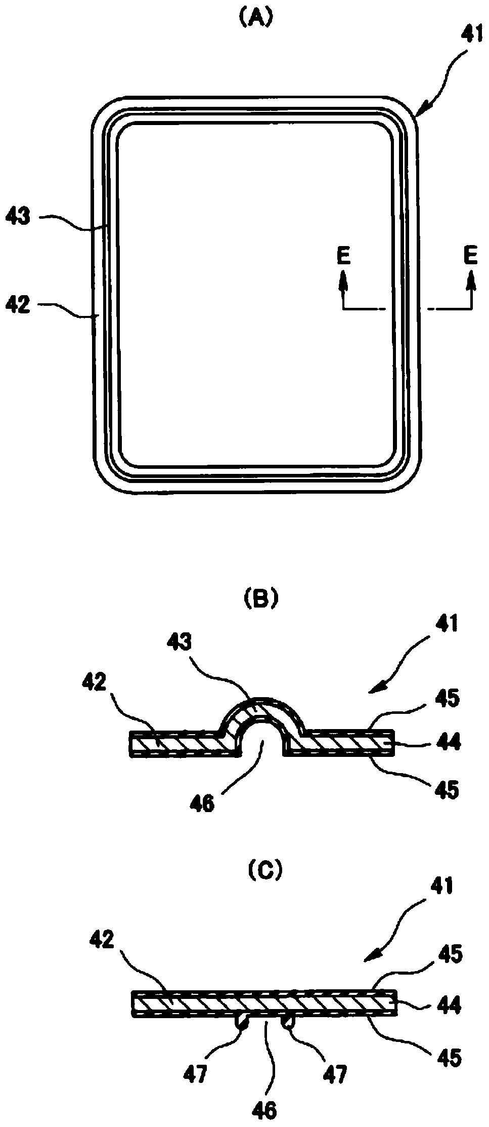
[0130] figure 1 The state before assembly of the sealing structure according to the first embodiment of the present invention is shown, and the frame body 11 , the grommet 21 , the cover 31 , and the metal substrate gasket 41 are drawn respectively. figure 2 (A) (B) (C) is the single figure of the retaining ring 21, image 3 (A) and (B) are a single view of the metal substrate gasket 41, Figure 4 (A) (B) and Figure 5 It is an explanatory diagram of the sealing structure. The sealing structure according to this embodiment is used to seal three-sided junctions in electrical equipment, engines, and the like, and is called a three-sided seal in terms of its function.

[0131]The frame body 11 is formed by a rigid material such as a predetermined metal or hard resin, and is provided with a vertical planar wall portion 12 as an upright portion on the side of the frame body. It is arranged in a way to penetrate the thickness direction of the wall. The grommet mounting portio...

no. 2 example …

[0149] Figure 7 The state before assembly of the sealing structure according to the second embodiment of the present invention is shown, and the frame body 11 , the grommet 21 , the cover 31 , and the metal substrate gasket 141 are drawn respectively. Figure 8 (A) (B) (C) is the single figure of the retaining ring 21, Figure 9 (A) (B) (C) is a single view of the metal substrate liner 141, Figure 10 (A) (B) and Figure 11 (A) is an explanatory diagram of the sealing structure. The sealing structure according to this embodiment is used to seal three-sided junctions in electrical equipment, engines, and the like, and is called a three-sided seal in terms of its function.

[0150]The frame body 11 is formed by a rigid material such as a predetermined metal or hard resin, and is provided with a vertical planar wall portion 12 as an upright portion on the side of the frame body. It is arranged in a way to penetrate the thickness direction of the wall. The grommet attachment...


PUM


Abstract

In order to prevent gaps from occurring in corner sections in a section where three surfaces are joined together, comprising the combination of a housing, grommet and cover, or the like, thereby improve sealing, a seal structure, which is provided with a housing in which a notch-shaped grommet-mounting section is disposed, a grommet, a cover and a metal substrate gasket, is provided, wherein the grommet is provided with a seal projection, and the seal projection forms a protruding section due to a portion of the seal projection protruding toward the metal substrate gasket when the seal projection makes intimate contact with the inner surface of the grommet-mounting section. The metal substrate gasket is provided with two seal lines and a groove-shaped recess between the seal lines. When nipped, the protruding section of the seal projection is tightly compressed inside the groove-shaped recess in the metal substrate gasket.

Description

technical field [0001] The invention relates to a sealing structure related to sealing technology. The sealing structure of the present invention is used, for example, to seal three-face joints in electrical equipment, engines, and the like. Background technique [0002] In electrical equipment such as electronic control units, power control units, or DC-DC converters for electric vehicles or hybrid vehicles, it is installed on the frame to seal the insertion openings of wiring and piping connected to the outside. Guard ring (refer to patent documents 1-3). [0003] which is, Figure 20 (A) is an explanatory diagram showing a typical conventional example, in which a notch-shaped grommet attachment portion 53 is provided on the wall portion 52 of the frame body 51 , and a grommet 54 is attached to the grommet attachment portion 53 . In addition, by covering the housing 51 and the grommet 54 with the cover 55 , the insertion openings of the above-mentioned wiring, piping, an...

Claims


Application Information

Patent Timeline
Patent Type & Authority Applications(China)
IPC IPC(8): H02G3/22F16J15/06F16J15/10H02G3/16H05K7/00
CPCF16J15/0818H05K5/069F16J15/08F16J2015/085F16J15/062H05K5/061F16J2015/0856H02G3/088
Inventor 高尾友纪三宅邦明中冈真哉新保范之
Owner NOK CORP
Why Eureka
Try Eureka