Eureka AIR delivers breakthrough ideas for toughest innovation challenges, trusted by R&D personnel around the world.

High-amperage energy storage device and method

Active Publication Date: 2008-02-21
MASSACHUSETTS INST OF TECH
View PDF9 Cites 147 Cited by
  • Summary
  • Abstract
  • Description
  • Claims
  • Application Information

AI Technical Summary

Benefits of technology

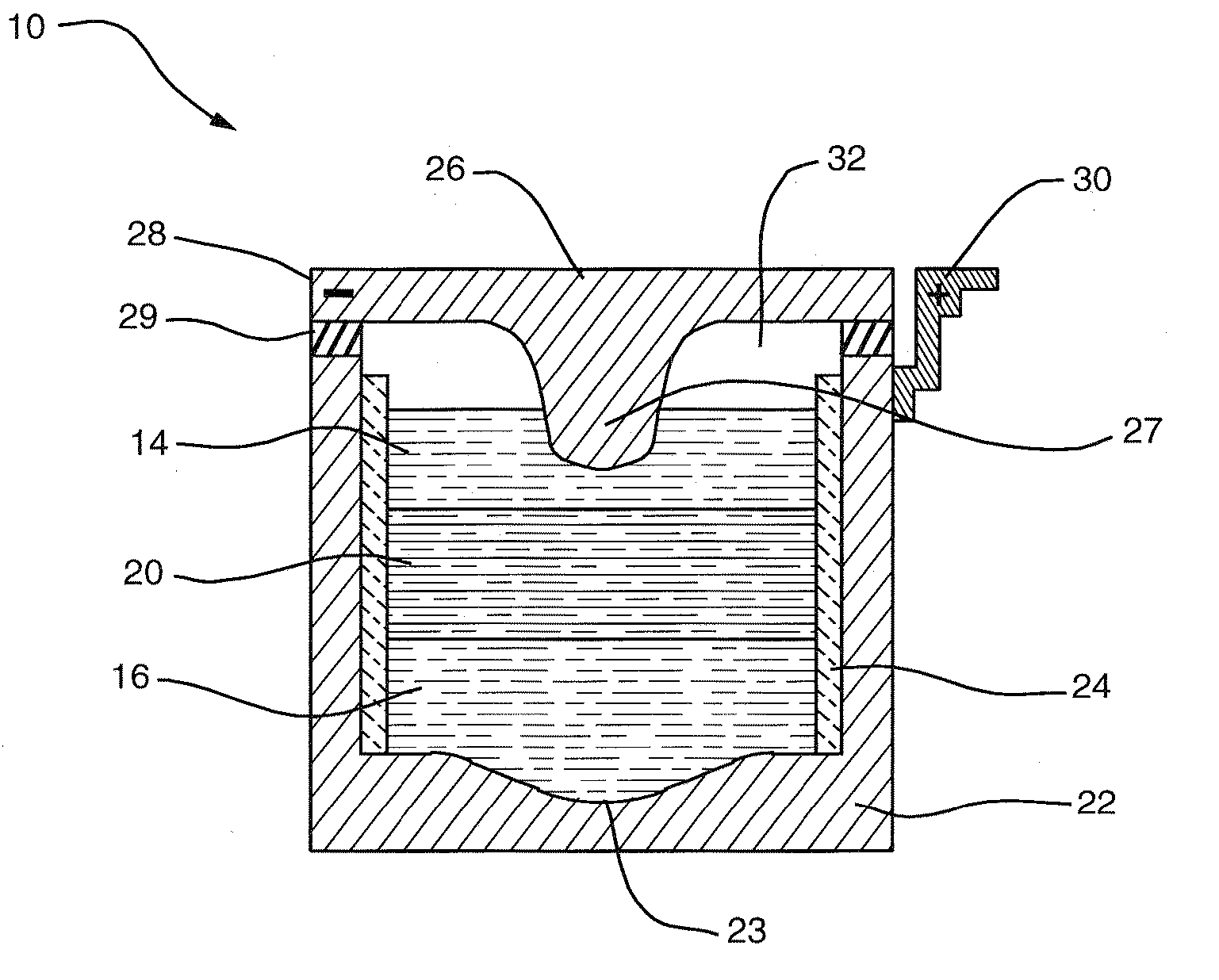
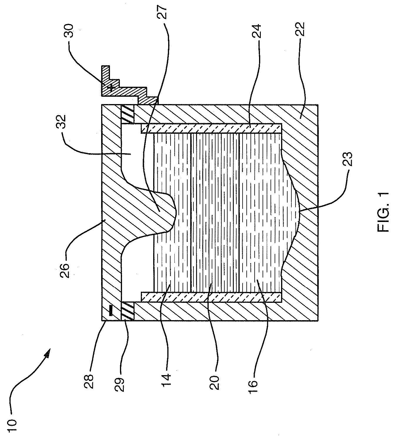
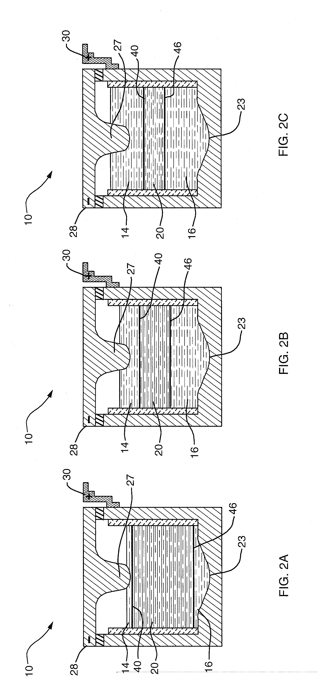
[0012] An aspect of this invention is that liquid-phase materials not heretofore used as components in an electrochemical cell can be anodically deposited. These anodically deposited liquid materials have electronic properties capacitating them to serve as an electrode in a cell. Namely, a metalloid—such as tellurium, antimony or bismuth—behaves as a nonmetal in forming compounds with metals. In the liquid phase, however, these metalloids behave as liquid metals in that they are electronic conductors. This confluence of properties makes possible the extraction of a liquid-phase electronic conductor from a molten salt by oxidation as part of ambipolar electrochemical metal extraction in which metal is also extracted by reduction at the electrode of opposite polarity.
[0017] The electrolyte of the invention may be a molten salt comprising the reaction compound and one or more supporting compounds in which the reaction compound is dissolved. The supporting compounds typically enhance ionic conductivity and / or inhibit electronic conductivity through the electrolyte.
[0019] The fact that the reactions at both electrodes occur entirely in the liquid state results in exceptionally high rate of reactions. When an electrochemical reaction involves species of different states of matter the kinetics of the reaction are constrained by the nucleation of products. For example, when a gas is produced there is an activation energy associated with the generation of gas on a solid substrate. Remedies include the use of catalysts in order to accelerate the rate of reaction. In stark contrast, the generation of liquid product from a liquid electrolyte without even the presence of a solid substrate at the site of reaction occurs at the highest reaction rates known to electrochemistry. The reaction is unimpeded by the nucleation of a foreign phase in a different state of matter. Furthermore, electronic conductivity of the liquid electrodes imparts fast kinetics to the cells of the invention through two means. In the first place, it enables electron transfer reactions to occur over the entire liquid element-electrolyte interfaces rather than being limited to triple-phase intersections. Secondly, it eliminates product diffusion away from the electrode, which is often a rate-limiting step in conventional batteries: when a metal ion in the melt gains electrons from the molten electrode, it instantly becomes part of the electrode. Furthermore, the high cell operating temperatures, greater than 500° C., or even greater than 700° C., necessary to exploit these chemistries facilitate reaction kinetics and ion migration. The accumulated contributions of these features are expected to produce current densities on the order of several amperes per square centimeter, rivaling those of electrochemical aluminum smelters, with efficiencies on the order of 80%.
[0026] The high-amperage energy storage technology of the invention is able to operate at extreme temperatures, such as arctic cold and desert heat, without restriction on geographical location and is realizable in a mobile structure. The all-liquid system is durable, avoiding common failure mechanisms experienced by systems that use a solid electrolyte or electrodes and / or involve a phase change. The power capacity is large and scalable for adaptation to a variety of large-scale and commercial power management applications.

Problems solved by technology

Balancing supply and demand of electrical energy over time and location is a huge unsolved problem in an array of applications all along the course from commercial generator to consumer.
The resulting systemic strain reduces the dependability of the supply, causing consumers inconvenience and loss of revenue.
Since most electrical energy generation in the United States relies on the combustion of fossil fuels, suboptimal management of electrical energy has a negative environmental impact through excessive emissions of pollutants and greenhouse gases.
Moreover, renewable energy sources like wind and solar power are active only intermittently, thus limiting the scale of their deployment in the absence of large-scale storage systems.
Although existing hydro-storage systems, mostly built 30 to 40 years ago, operate relatively inexpensively, they are expensive to build.
Also, a reservoir sufficient to support an 8-hour discharge translates to a sizeable physical footprint.
The technology is inflexible with respect to location, limited to siting on a large, unpopulated flat-topped mountain near an urban setting and close to existing transmission lines.
Although they are the cheapest commercial battery technology on the market, their limited cycle life, on the order of several hundred charge-discharge cycles, limits their performance in uses involving frequent activation, such as daily power management.
They do not respond well to fast charging or discharging, which lowers their efficiency and reduces their lifespan, as does deep discharge cycling.
The technology provides a sufficiently compact apparatus that exhibits an acceptable cycle-life for daily deep-discharges, but there are downsides.
The sponge electrode is difficult to manufacture and susceptible to corrosion.
The ceramic electrolyte material is fragile and sensitive to thermal shock.
Also, large ceramic bodies of thin cross section are difficult and costly to manufacture.
Thus, the design of the cell is constrained by tradeoffs among conductivity, reliability, and ease of manufacturing, so that the cells are not really scalable.
Due to the resulting electrolyte size limitations, multiple cells are assembled into long cylinders.
Using an array of such a large number of cells complicates integration with, and increases the cost of, the power electronics for interfacing with an AC system.
Despite a longfelt need, a robust energy storage device combining capacity, economy, flexibility and long life has not emerged.

Method used


Image

  • High-amperage energy storage device and method
  • High-amperage energy storage device and method
  • High-amperage energy storage device and method

Examples


Embodiment Construction

[0034] The deployment of high-amperage electrical energy storage equipment, capable of rapidly receiving and dispatching electricity, could play a revolutionary role in addressing the market and societal impacts of supply-demand mismatch. However, a single storage technology adaptable to assorted needs along the distribution trajectory has been elusive. Although details vary according to the individual application, the features desirable in an electrical energy storage technologies for addressing large-scale supply and demand variabilities include the following: physical footprint smaller than about 100 m2 / MW; robustness with respect to movement and changes in environment; cycle life greater than 3000 deep discharge cycles; lifespan of 10 to 15 years; DC-to-DC efficiency of about 75% to 85%; power capacity from about 10 kW to greater than 10 MW; discharge capacity from about 4 to 10 hours; response time less than 100 ms; minimal maintenance; zero noise and zero emissions.

[0035] The...


PUM


Abstract

An electrochemical method and apparatus for high-amperage electrical energy storage features a high-temperature, all-liquid chemistry. The reaction products created during charging remain part of the electrodes during storage for discharge on demand. In a simultaneous ambipolar electrodeposition cell, a reaction compound is electrolyzed to effect transfer from an external power source; the electrode elements are electrodissolved during discharge.

Description

CROSS-REFERENCE TO RELATED APPLICATION [0001] The present application claims the benefit of U.S. Provisional Patent Application Ser. No. 60 / 837,657, which was filed on Aug. 15, 2006, by Donald R. Sadoway et al. for a HIGH-AMPERAGE ENERGY STORAGE DEVICE and is hereby incorporated by reference.BACKGROUND OF THE INVENTION [0002] 1. Field of the Invention [0003] The invention relates to high-capacity electrical energy storage. In particular, this invention provides novel electrochemical cells and batteries for large-scale and commercial energy management. More particularly, techniques for delivering and receiving electrical energy by simultaneous ambipolar reversible electrochemical metal extraction in a high-temperature, all-liquid system is described. [0004] 2. Background Information [0005] Balancing supply and demand of electrical energy over time and location is a huge unsolved problem in an array of applications all along the course from commercial generator to consumer. The result...

Claims


Application Information

Patent Timeline
IPC IPC(8): H01M10/36
CPCH01M2/0252H01M10/04H01M10/399H01M10/39H01M10/049H01M50/138Y02E60/10Y02P70/50
Inventor SADOWAY, DONALDCEDER, GERBRANDBRADWELL, DAVID
Owner MASSACHUSETTS INST OF TECH
Why Eureka
Eureka Blog
Learn More