
Reconfigurable processing

a reconfigurable processing and processing technology, applied in the field of reconfigurable processing, can solve the problems of poor hardware reutilization for other applications, poor on-chip network architecture, computational intensive multi-media and graphics applications, etc., and achieve the effects of reducing the total area, reducing the length of the wire, and reducing the delay of the signal

Active Publication Date: 2007-08-23
ARIZONA STATE UNIVERSITY
View PDF13 Cites 183 Cited by
  • Summary
  • Abstract
  • Description
  • Claims
  • Application Information

AI Technical Summary

Benefits of technology

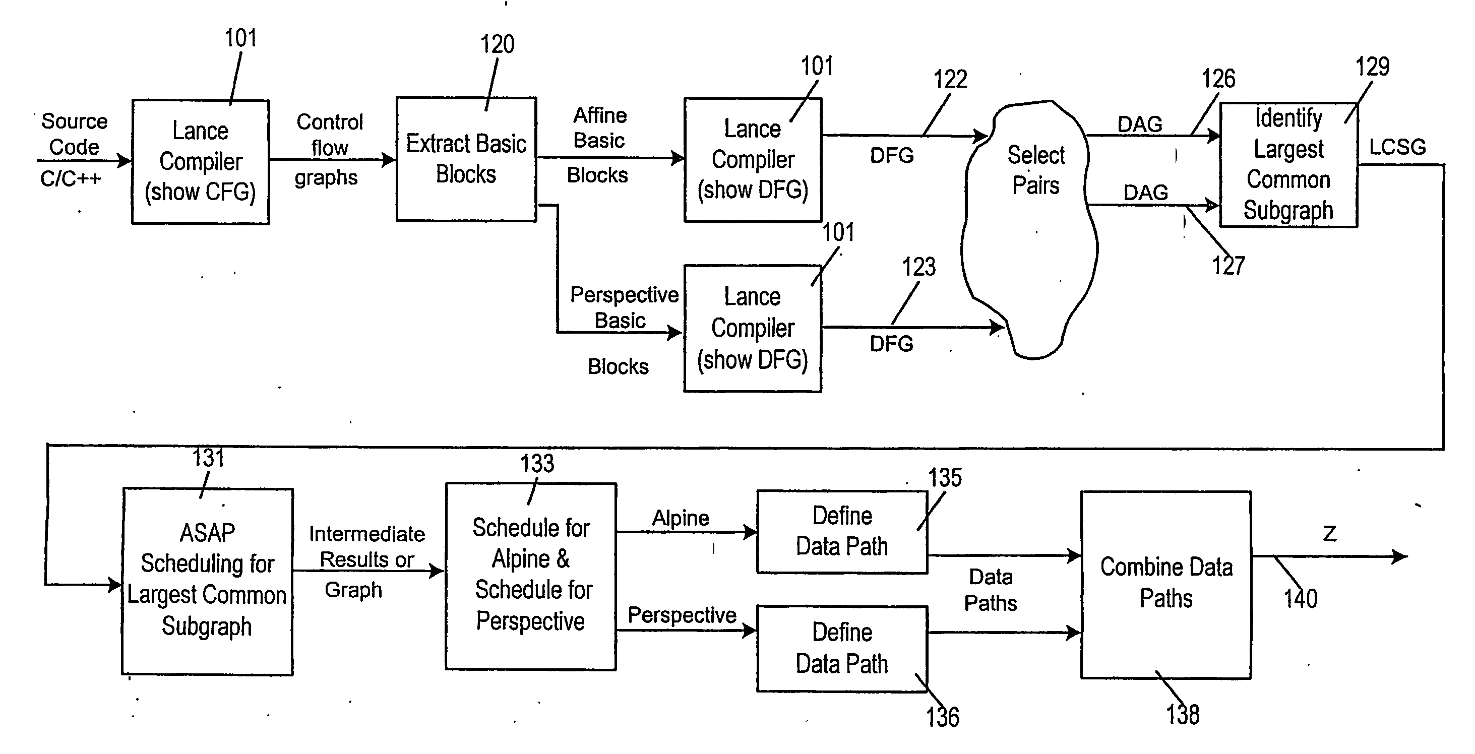
[0051] In accordance with this invention, designing processing elements based on identifying correlated compute intensive regions within each application and between applications results in large amounts of processing in localized regions of the chip. This reduces the amount of reconfigurations and hence faster application switching. This also reduces the amount of on-chip communication, which in turn helps reduce power consumption. Since applications can be represented as Control Data Flow Graphs (CDFGs) such a pre-processing analysis lies in the area of pattern matching, specifically graph matching. In this context a reduced complexity, yet exhaustive enough graph matching algorithm is provided. The amount of on-chip communication is reduced by adopting reconfiguration aware static scheduling to manage task and resource dependencies on the processor. This is complemented by a divide and conquer approach which helps in the allocation of an appropriate number of processing units aimed towards achieving uniform resource utilization.
[0054] At this point, it will be appreciated, the utilization of the hardware that represents the ASAP-scheduled largest common subgraph by the operations of each implicated intermediate flow graph needs scheduling. Bearing in mind duration of use of the hardware representing the largest common subgraph by the operations of each of the implicated intermediate flow graphs, hardware usage is scheduled for fastest completion of the combined software and hardware of operations of all affected intermediate flow graph as represented in the combined data patches. Method of scheduling according to the present invention treats reconfiguration edges in the same way as communication edges and includes the reconfiguration overhead while determining critical paths. This enables employment of the best CDFG scheduling technique and incorporation of the reconfiguration edges.
[0058] The steps of component layout and interconnectivity involve (1) partitioning—cluster recognition and extraction, (2) placement—the location of components in the available area on a chip, and (3) routing—the interconnection of components via conductors and switches with the goal of maximum speed and minimum power consumption.

Problems solved by technology

Multimedia and graphics applications are computationally intensive and have been traditionally solved in 3 different ways.
The latter, albeit faster and more power, area and time efficient for a specific application, offers poor hardware reutilization for other applications.
But poor on-chip network architectures lead to high reconfiguration times and power consumptions.
This is one of the important factors that leads to the large overall configuration times and high power consumption compared to ASIC or embedded processor solutions.
Multimedia computing presents challenges from the perspectives of both hardware and software.
The results show that there are significant variations in the computational complexity among the various modes / operations of MPEG-4.
Therefore for rapid configuration, off-chip context loading becomes slow due to the large amount of configuration data that must be transferred across a limited bandwidth I / O path.
However, if the architectural granularity is larger than the task granularity, the device's computational power will be under utilized.
Most of the current approaches towards building a reconfigurable processor are targeted towards performance in terms of speed and are not tuned for power awareness or configuration time optimization.
None of the current approaches attempt to identify the regions through an automated low complexity approach that deals with Control Data Flow Graphs (CDFGs).
Secondly, the number of levels in hierarchical network architecture must be influenced by the number of processing elements or CLUs needed to complete the task / application.
Thirdly, the complex network on the chip, makes dynamic scheduling expensive as it adds to the primary burden of power dissipation through routing resource utilization.
Most of the current applications provide a large amount of variations to users and hence are control-dominated.
To arrive at an optimal static schedule for such an application would involve a highly complex scheduling algorithm.
But, a static schedule is always worse than a dynamic schedule in terms of optimality.
The problem with this approach is that it is applicable only to small graphs and also restricted to S-graphs and trees.
The advantages are that it is optimal, but it has the drawback of being quite complex.
But, a major limiting factor is that the schedule information needs to be communicated to all the processing elements on the chip at all time.
But the drawback is that the control mechanism for having knowledge of each iteration and the resource handling that iteration is very complicated.
But in our case, the network occupies about 70% of the chip area [6] and hence cannot afford to communicate with each other too often.
Moreover the granularity level of operation between processing elements is beyond a basic block level and hence this method is not practical.
A major limitation of this method is that it requires knowing the target architecture while designing the rearrangement techniques.
A main drawback is that this method does not apply for CDFG scheduling.
This method is not suited for our purpose which needs real-time performance.
Though the complexity of this algorithm is less, the schedule is nowhere near optimal.
An analysis of the existing work on scheduling techniques for reconfigurable architectures has shown that there is not enough work done on static scheduling techniques for CDFGs.
Despite advances in VLSI design automation, the time it takes to market for a chip is unacceptable for many applications.
The key problem is time taken due to fabrication of chips and therefore there is a need to find new technologies, which minimize the fabrication time.
However fabrication time for gate arrays is still unacceptable for several applications.
This problem depends on the architecture in which the circuit has to be implemented.
Physical design is a very complex process and therefore it is usually broken into various subsets.
Layout of the entire circuit cannot be handled due to the limitation of memory space as well as computation power available.
Placement may lead to un-routable design.
This is due to the fact that once the position of the block is fixed; there is not much to do to improve the routing and the circuit performance.
As a result this approach is very sensitive to the order of the nets that are considered for routing.
However sequencing techniques don't solve the net ordering problem satisfactorily.
This may also not solve the net ordering problem so in addition to that ‘rip-up and reroute’ technique [Bol79, DK82] and ‘shove-aside’ techniques are used.

Method used


Image

  • Reconfigurable processing
  • Reconfigurable processing
  • Reconfigurable processing

Examples


case 1

ry loops with unknown execution time. Here, the problem is the execution time of the process is known only after it has finished executing in the processor. So static scheduling is not possible.

[0327] Solution: (Assumption) Once a unit generates an output, this data is stored at the consuming / target unit's input buffer. Referring to the scheduled chart of FIG. 24X, each row represents processes scheduled on a unique type of unit (Processing Element). Let P1 be the loopy process.

[0328] From FIG. 24X we see that

[0329] P3 depends on P1 and P4,

[0330] P2 depends on P1,

[0331] P6 depends on P2 and P5.

[0332] If P1's lifetime exceeds the assumed lifetime (most probable lifetime or a unit iteration), then all dependents of P1 and their dependents (both resource and data) should be notified and the respective Network Schedule Manager (NSM) and Logic Schedule Manager (LSM), of FIG. 27X, should be delayed. Of course, this implies that while preparing the schedule tables, 2 assumptions are m...

case 2

ination of two loops with one loop feeding data to the other in an iterative manner.

[0338] Solution: Consider a processing element, PA, feeding data to a processing element, PB, in such a manner. For doing static scheduling, if one loop unrolls them and treats it in a manner of smaller individual processes, then it is not possible to assume an unpredictable number of iterations. Therefore if an unpredictable number of iterations is assumed in both loops, then the memory foot-print could become a serious issue. But an exception can be made. If both loops at all times run for the same number of iterations, then the schedule table must initially assume either the most probable number of iterations or one iteration each and schedule PA,PB,PA,PB and so on in a particular column. In case the prediction is exceeded or fallen short off, then the NSM and LSMs must do 2 tasks:

[0339] 1) If the iterations exceed expectations, then all further dependent processes (data and resource) must be not...

case 3

in the macro level i.e. containing more than a single process.

[0342] Solution: In this case, there are some control nodes inside a loop. Hence the execution time of the loop changes with each iteration. This is a much more complicated case than the previous options. Here lets consider a situation where there is a loop covering two mutually exclusive paths, each path consisting of two processes (A,B and C,D) with (3,7 and 15,5) cycle times. In the schedule table there will be a column to indicate an entry into the loop and two columns to indicate the paths inside the loop. Optimality in scheduling inside the loop can be achieved, but in the global scheme of scheduling, the solution is non-optimal. But this cannot be helped because to obtain a globally optimal solution, all possible paths have to be unrolled and statically scheduled. This results in a table explosion and is not feasible in situations where infinite number of entries in table are not possible. Hence, from a global view...


PUM


Abstract

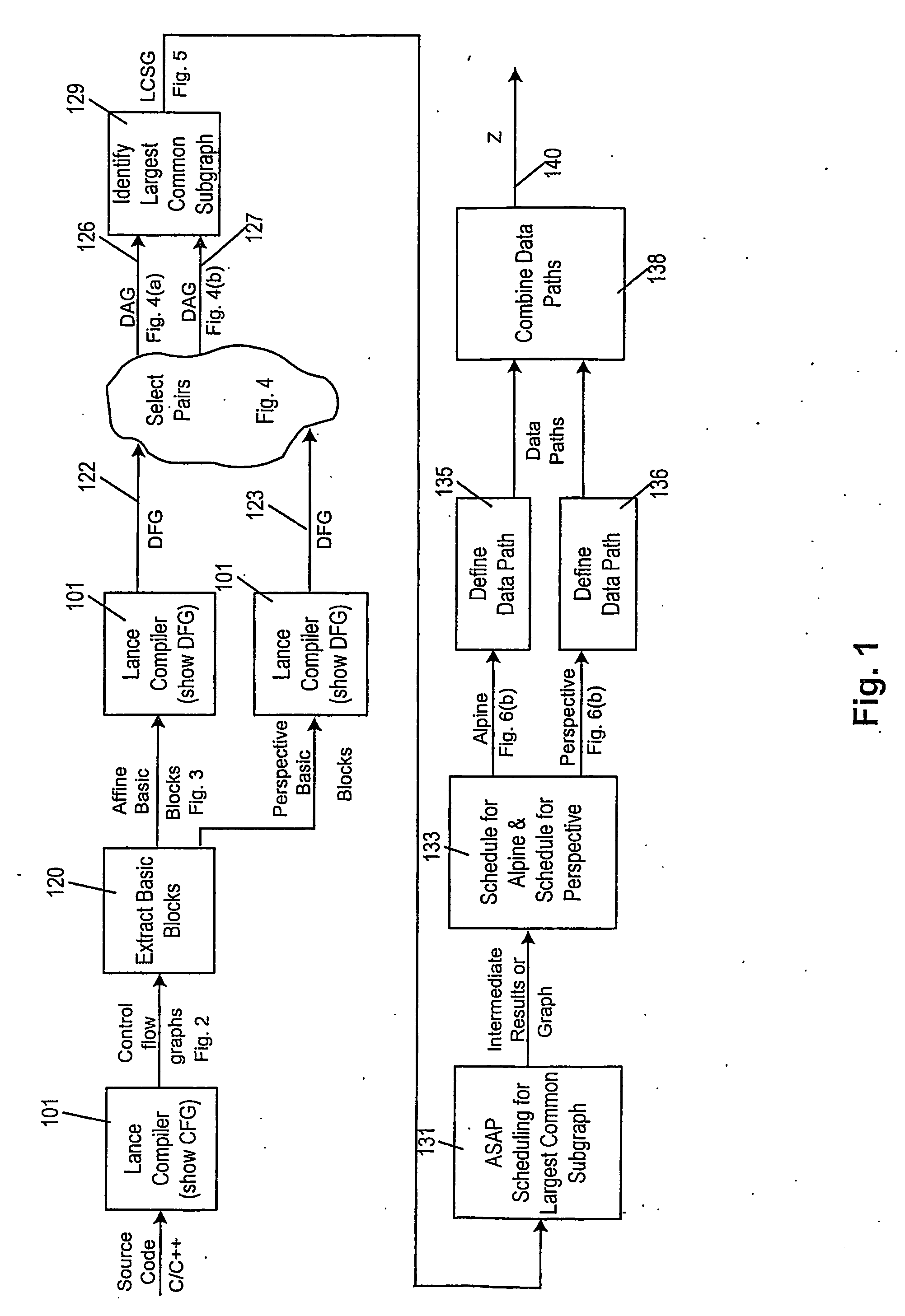
A method of producing a reconfigurable circuit device for running a computer program of moderate complexity such as multimedia processing. Code for the application is compiled into Control Flow Graphs representing distinct parts of the application to be run. From those Control Flow Graphs are extracted basic blocks. The basic blocks are converted to Data Flow Graphs by a compiler utility. From two or more Data Flow Graphs, a largest common subgraph is determined. The largest common subgraph is ASAP scheduled and substituted back into the Data Flow Graphs which also have been scheduled. The separate Data Flow Graphs containing the scheduled largest common subgraph are converted to data paths that are then combined to form code for operating the application. The largest common subgraph is effected in hardware that is shared among the parts of the application from which the Data Flow Graphs were developed. Scheduling of the overall code is effected for sequencing, providing fastest run times and the code is implemented in hardware by partitioning and placement of processing elements on a chip and design of the connective fabric for the design elements.

Description

CROSS-REFERENCE TO RELATED APPLICATIONS [0001] This application claims priority from provisional patent application Ser. No. 60 / 445,339 filed Feb. 5, 2003 in the name of Aravind R. Dasu et al. entitled “Reconfigurable Processing,” provisional patent application Ser. No. 60 / 490,162 filed Jul. 24, 2003 in the name of Aravind R. Dasu et al. entitled “Algorithm Design for Zone Pattern Matching to Generate Cluster Modules and Control Data Flow Based Task Scheduling of the Modules,” provisional patent application Ser. No. 60 / 493,132 filed Aug. 6, 2003 in the name of Aravind R. Dasu et al. entitled “Heterogeneous Hierarchical Routing Architecture,” and provisional patent application Ser. No. 60 / 523,462 filed Nov. 18, 2003 in the name of Aravind R. Dasu et al. entitled “Methodology to Design a Dynamically Reconfigurable Processor,” all of which are incorporated herein by reference.FIELD OF THE INVENTION [0002] This invention relates to the accomplishment of moderately complex computer appli...

Claims


Application Information

Patent Timeline
Patent Type & Authority Applications(United States)
IPC IPC(8): G06F9/45G06FG06F17/50
CPCG06F8/433Y02B60/181G06F17/5045G06F8/4432G06F30/30Y02D10/00
Inventor DASU, ARAVINDRAKOGLU, ALISUDARSANAM, ARVINDPANCHANATHAN, SETHURAMAN
Owner ARIZONA STATE UNIVERSITY
Learn More