Powder injection molding of glass and glass-ceramics
a technology of glass-based materials and injection molding, which is applied in the field of glass-based ceramics manufacturing, can solve the problems of difficult etching, machine or other form by subtractive forming processes, difficult to produce complex shapes in such materials, and little attention to powder injection molding of glass-based materials, etc., and achieve good shape retention and surface properties
- Summary
- Abstract
- Description
- Claims
- Application Information
AI Technical Summary
Benefits of technology
Problems solved by technology
Method used
Image
Examples
example 1
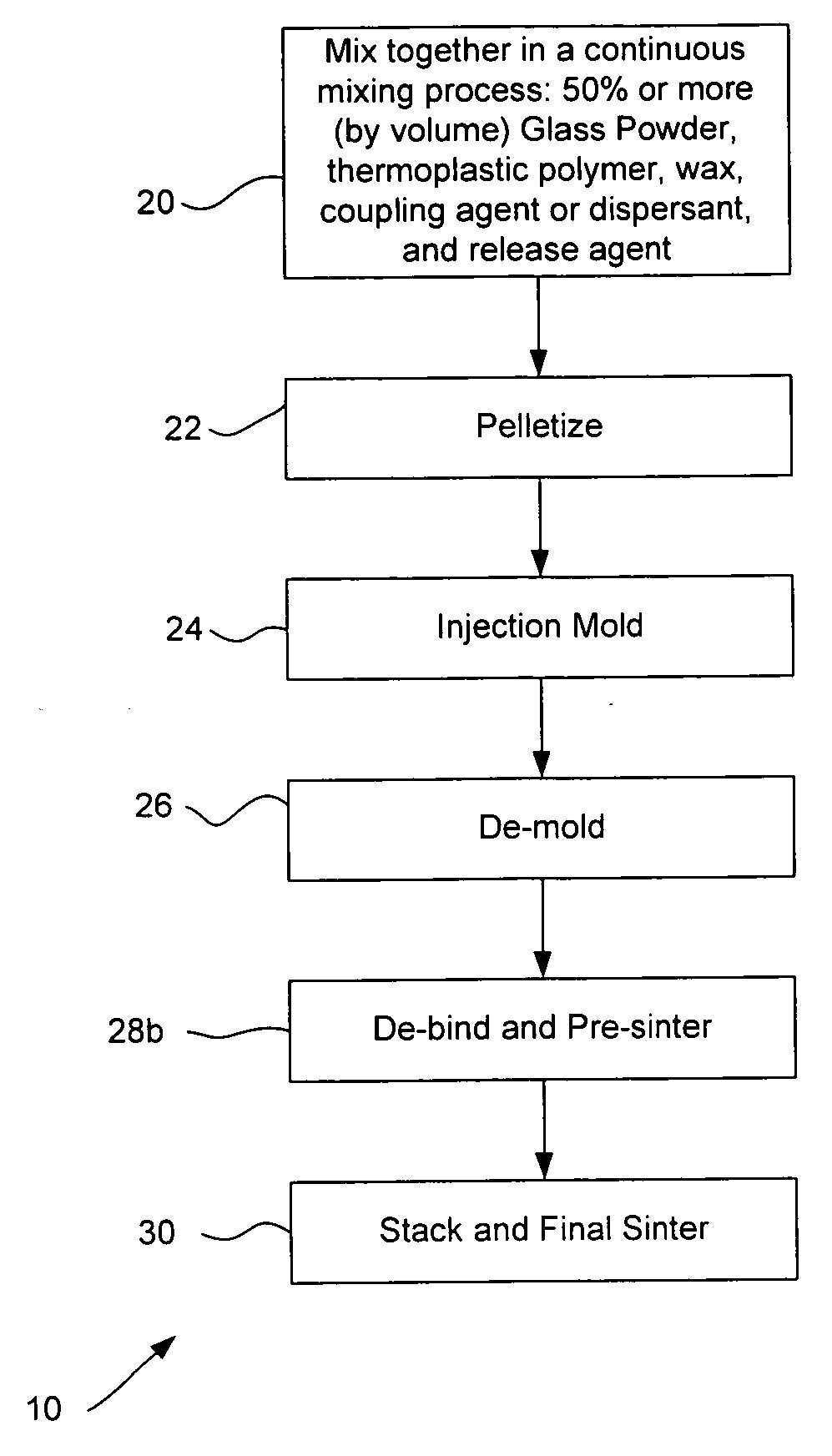
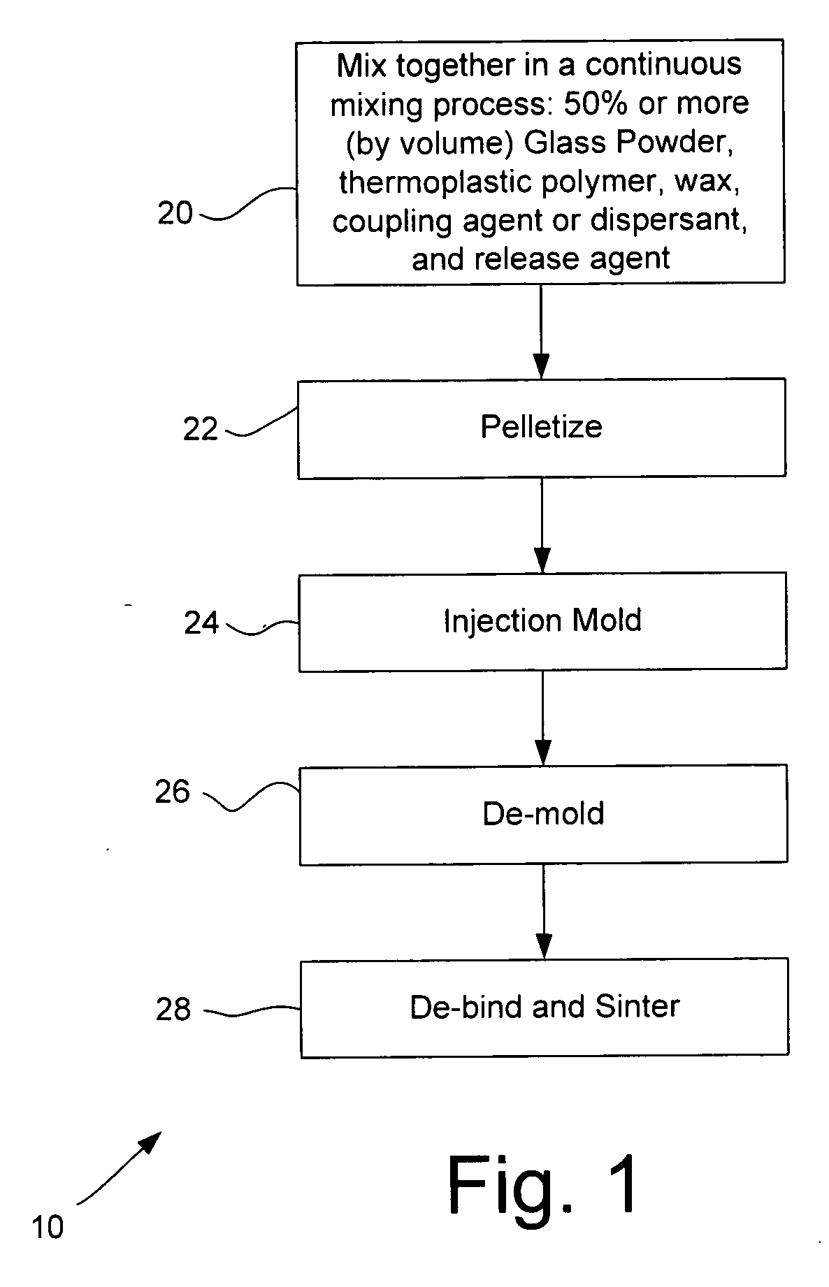
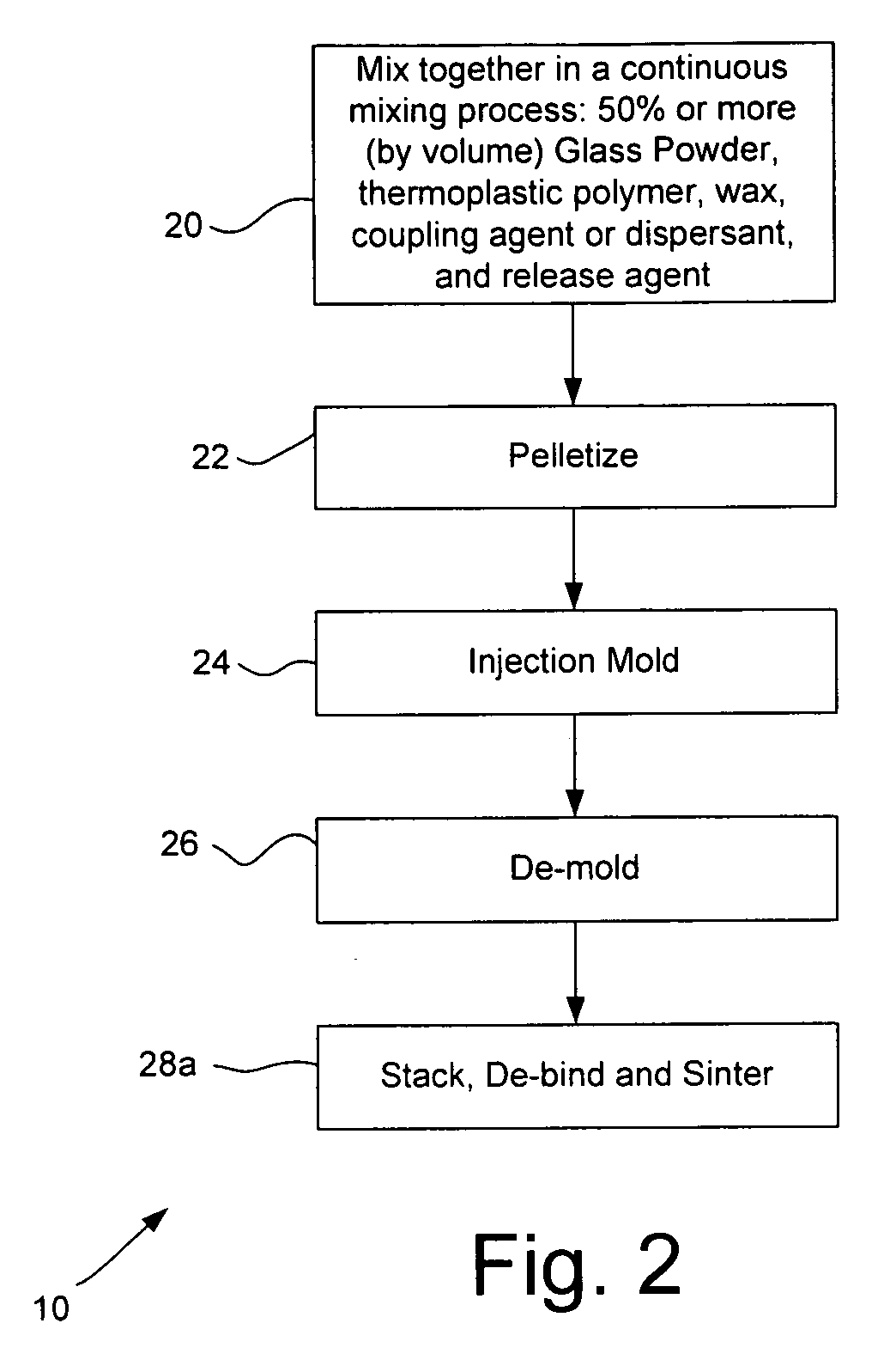
[0041] Feedstocks were prepared in accordance with the methods outlined above, with various glass powders including powders of Corning glasses codes 7740, 7913, 7761 (Corning, N.Y., USA). Powder particle sizes were varied from 90%<10 um to 90%<60 um. Part molding (by injection molding), stacking, de-binding and sintering was performed. The process of the present invention provided good performance regardless of glass type, particle size, and particle size distribution within these ranges. Successful results for both sintering and stacking then sintering were obtained with glass various compositions, including compositions that remain amorphous, compositions that phase separate, and compositions that crystallize during sintering, demonstrating the versatility and wide application of the process for forming articles of both glass and glass-ceramic materials.
[0042] The process described above in conjunction with FIGS. 1-3 was used to produce closed microfluidic structures of the type ...
example 2
[0043] The process described above in conjunction with FIGS. 1-3 was further used to produce closed microfluidic structures of the type shown in part in FIGS. 4-7 using code 7913 glass available from Corning Incorporated, Corning, N.Y. USA. Molded parts were debinded and sintered in an electric furnace with using the following schedule: Ramp to 225° C. at 2° C. / minute; Hold 1 hour; Ramp to 1105° C. at 2° C. / minute; Hold 60 minutes; Cool to ambient at furnace's natural rate.
[0044]FIG. 6 shows a cross-sectional digital image of resulting sintered-together layers 40 and 42. The layers are adhered at wall structures 44 that stood originally on layer 40. FIG. 7 shows a close-up of one of the joints layer 40 and layer 42 are joined via wall structure 44, with the joint lying at the joint position indicate by the arrow J. As seen from the figure the area of the joint is well sealed and well joined. This illustrates the suitability of the inventive process for the formation of multi-part s...
example 3
[0045] Fifty-seven single-layer molded parts were injection molded and ten parts sampled from the fifty-seven were sintered according to the process described above. Post-sintering dimensional variation was limited to 138.14±0.36 mm (0.26%) in length and 91.80±0.27 mm (0.29%) in width. For the sample of ten, sintering shrinkage was 9.1±0.3% for eleven selected local dimensions spread across the surface of the part.
PUM
| Property | Measurement | Unit |
|---|---|---|
| Percent by volume | aaaaa | aaaaa |
| Percent by volume | aaaaa | aaaaa |
| Percent by volume | aaaaa | aaaaa |
Abstract
Description
Claims
Application Information
 - R&D
- Intellectual Property
- Life Sciences
- Materials
- Tech Scout
- Unparalleled Data Quality
- Higher Quality Content
- 60% Fewer Hallucinations
Browse by: Latest US Patents, China's latest patents, Technical Efficacy Thesaurus, Application Domain, Technology Topic, Popular Technical Reports.
© 2025 PatSnap. All rights reserved.Legal|Privacy policy|Modern Slavery Act Transparency Statement|Sitemap|About US| Contact US: help@patsnap.com


