R-T-B type alloy, production method of R-T-B type alloy flake, fine powder for R-T-B type rare earth permanent magnet, and R-T-B type rare earth permanent magnet

Active Publication Date: 2007-05-03
TDK CORPARATION
View PDF8 Cites 9 Cited by
  • Summary
  • Abstract
  • Description
  • Claims
  • Application Information

AI Technical Summary

Benefits of technology

[0021] The present inventors have particularly observed the cross-sectional texture of alloy flakes which are cast and solidified under various conditions, and found that there is a relationship between the precipitated state of 2-17 phase and the magnetic characteristics and when a fine 2-17 phase (R2T17 phase) is precipitated in the alloy, the magnetic characteristics can be enhanced.
[0022] Also, the present inventors have confirmed the fact that when a sintered magnet is produced from an alloy allowing for the presence of a fine R2T17 phase or an alloy prepared by controlling the cooling rate on the casting roll or the temperature on separating from the casting roll in the SC method, the coercive force thereof is stably increased and excellent magnetic characteristics are obtained. The present invention has been accomplished based on these findings.

Problems solved by technology

Accordingly, if the R-rich phase in the shaped magnet is in a poorly dispersed state, it incurs local failure of sintering or reduction of magnetism.
Another problem encountered in casting an R-T-B type alloy is production of α-Fe in the cast alloy.
The α-Fe has deformability and remains in the grinder without being ground, and this not only decreases the grinding efficiency at the grinding of alloy but also affects the compositional fluctuation or particle size distribution.
However, α-Fe is present as a peritectic nucleus and therefore, its elimination requires solid phase diffusion for a long time.
In the case of an ingot having a thickness of several cm and a rare earth content of 33% or less, elimination of α-Fe is practically impossible.
Also, it has been found that fine division readily occurs in the region where the R-rich phase produced on the mold face side in the alloy (fine R-rich phase region) is extremely finely dispersed, as a result, the grinding stability of the alloy is deteriorated and at the same time, the particle size distribution of the powder is broadened.

Method used


Image

  • R-T-B type alloy, production method of R-T-B type alloy flake, fine powder for R-T-B type rare earth permanent magnet, and R-T-B type rare earth permanent magnet
  • R-T-B type alloy, production method of R-T-B type alloy flake, fine powder for R-T-B type rare earth permanent magnet, and R-T-B type rare earth permanent magnet
  • R-T-B type alloy, production method of R-T-B type alloy flake, fine powder for R-T-B type rare earth permanent magnet, and R-T-B type rare earth permanent magnet

Examples


example 1

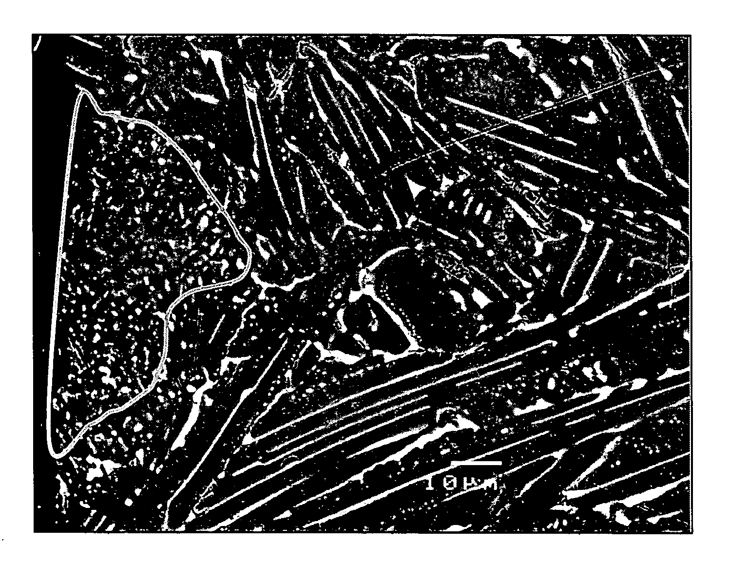
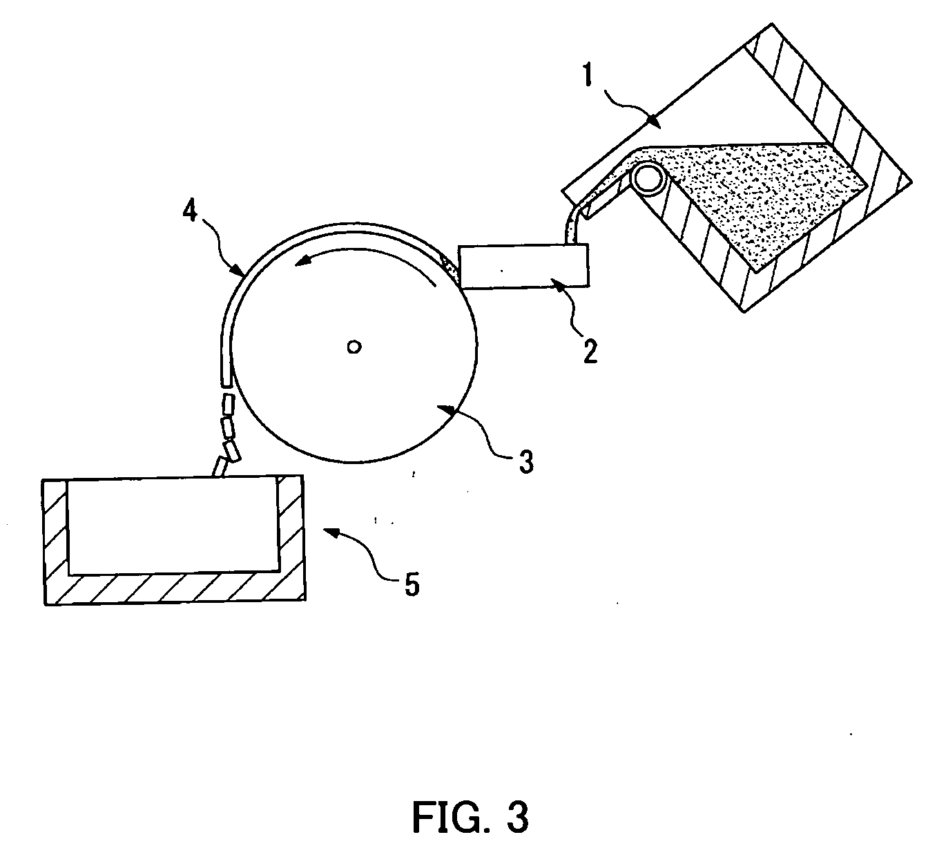
[0086] Raw materials of metallic neodymium, metallic dysprosium, ferroboron, cobalt, aluminum, copper and iron were provided to give an alloy composition comprising, in terms of weight ratio, 22% of Nd, 9% of Dy, 0.95% of B, 1% of Co, 0.3% of Al and 0.1% of Cu, with the balance being Fe. The raw materials were melted in an alumina crucible in an argon gas atmosphere at 1 atm by using a high-frequency melting furnace, and the molten alloy was cast by the SC method to produce an alloy flake.

[0087] The rotating roll for casting had a diameter of 600 mm and was made of an alloy obtained by mixing slight amounts of Cr and Zr with copper, and the inside thereof was water-cooled. The peripheral velocity of the roll at the casting was 1.3 m / sec, the average molten alloy supply rate to the casting roll was 28 g / sec per 1-cm width, and the average temperature of the alloy on separating from the casting roll was measured by a radiation thermometer and found to be 890° C. In the measured value...

example 2

[0095] Metallic neodymium, metallic praseodymium, ferroboron, cobalt, aluminum, copper and iron were blended to give an alloy composition comprising, in terms of weight ratio, 26.0% of Nd, 5.0% of Pr, 0.95% of B, 1.0% of Co, 0.3% of Al and 0.1% of Cu, with the balance being Fe. Melting and casting were performed by the SC method in the same manner as in Example 1. However, the peripheral velocity of the roll at the casting was 1.3 m / sec, the average molten alloy supply rate to the casting roll was 28 g / sec per 1-cm width, the average temperature of the alloy on separating from the casting roll, measured by a radiation thermometer, was 850° C., and the difference between the maximum temperature and the minimum temperature of the measured values was 20° C. Since the melting point of the R2T14B phase of this alloy is about 1,140° C., the difference from the average separation temperature is 290° C. Also, the average cooling rate of the R-T-B type alloy on the casting roll was 1,060° C....

example 3

[0102] The alloy flake obtained in Example 1 was subjected to hydrogen cracking and pulverization by a jet mill. The conditions in the hydrogen absorption step as the pre-step of the hydrogen cracking step were a 100% hydrogen atmosphere, a pressure of 2 atm, and a holding time of 1 hour. The temperature of the metal strip at the initiation of a hydrogen absorption reaction was 25° C. The conditions in the dehydrogenation step as the post-step were an in-vacuum atmosphere of 0.133 hPa, 500° C. and a holding time of 1 hour. Subsequently, 0.07 mass % of a zinc stearate powder was added to the powder obtained above, and the resulting powder was thoroughly mixed by a V-type blender in a 100% nitrogen atmosphere and then pulverized by a jet mill. The atmosphere at the grinding was a nitrogen atmosphere having mixed therein 4,000 ppm of oxygen. Thereafter, the powder was again thoroughly mixed by a V-type blender in a 100% nitrogen atmosphere. The oxygen concentration in the obtained powd...


PUM

PropertyMeasurementUnit
Temperatureaaaaaaaaaa
Fractionaaaaaaaaaa
Fractionaaaaaaaaaa

Abstract

An R-T-B type alloy (wherein R is at least one member selected from rare earth elements, T is a transition metal including Fe, and B includes boron) which is a raw material for use in a rare earth-based permanent magnet, wherein the volume percentage of the region containing an R2T17 phase having an average grain diameter of 3 μm or less in the short axis direction is from 0.5 to 10%.

Description

CROSS-REFERENCE TO RELATED APPLICATIONS [0001] This application claims the benefit of U.S. Provisional Application No. 60 / 734,770, filed Nov. 9, 2005, the content of which is incorporated herein by reference. In addition, the present application claims foreign priority based on Japanese Patent Application No. 2005-316551, filed Oct. 31, 2005, the content of which is incorporated herein by reference.TECHNICAL FIELD [0002] The present invention relates to an R-T-B type alloy, a production method of an R-T-B type alloy flake, a fine powder for an R-T-B type rare earth permanent magnet, and an R-T-B type rare earth permanent magnet. In particular, the present invention relates to an R-T-B type alloy flake produced by a strip casting method. BACKGROUND ART [0003] Among permanent magnets, R-T-B type magnets exhibit a high maximum magnetic energy product and are being used for HD (hard disk), MRI (magnetic resonance imaging), various types of motors and the like by virtue of their high-per...

Claims


Application Information

Patent Timeline
IPC IPC(8): H01F1/057
CPCB22F9/10B22F2009/044B22F2998/10B22F2999/00C22C1/0491C22C38/005C22C38/06C22C38/10C22C38/16C22C2202/02H01F1/0573H01F1/0577H01F41/0273B22F1/0055B22F9/023B22F9/04C22C1/047B22F1/068
Inventor SASAKI, SHIROHASEGAWA, HIROSHINAKAJIMA, KENICHIRO
Owner TDK CORPARATION
Why Eureka
Try Eureka