Electromechanical transducer

a transducer and electromechanical technology, applied in the field of electromechanical transducers, can solve the problems of difficult to realize an electromechanical transducer having a large driving force relative to an input power, difficult to set the stiffness of the restoring force of the armature to be close to the negative stiffness, etc., to reduce the influence of shock resistance, increase the driving force, and process relatively easy

Active Publication Date: 2017-08-24
RION COMPANY
View PDF2 Cites 10 Cited by
  • Summary
  • Abstract
  • Description
  • Claims
  • Application Information

AI Technical Summary

Benefits of technology

[0009]According to the electromechanical transducer of the invention, the armature, which is positioned at a balanced position when no current flows in the coil, is displaced relative to the structural unit due to the magnetic force applied to the inner portion when the current flows in the coil, and at this point, each of the first and second elastic units gives the restoring force acting on the armature. Meanwhile, if external force is applied to the armature so as to displace the armature when no current flows in the coil, the magnetic flux in the first direction is generated, and if the amount of the displacement becomes large, the magnetic flux is restricted to a portion at which the cross-sectional area of the armature is small so that the magnetic flux is saturated. Thus, since a difference between the maximum value of negative stiffness acting on the armature and the negative stiffness at the balanced position can be small, it is possible to sufficiently increase a driving force of the electromechanical transducer relative to an input power.
[0010]The armature of the invention can be formed in various shapes as long as the above condition of the cross-sectional area is satisfied. For example, a width of the armature in a second direction perpendicular to the first direction and the displacement direction may be smaller at the predetermined position than at the two regions. In this case, the armature is preferably a plate-like member having a constant thickness in the displacement direction. Thereby, the armature having a shape of partially narrow width can be processed relatively easy, and it is possible to reduce influence on shock resistance in comparison with thinning the armature. In addition, as a planer shape of the armature, there can be formed concave portions symmetrically arranged on both sides in the second direction in the inner portion of the armature.
[0011]In the invention, the magnetic circuit can be configured using at least one pair of magnets in the two regions of the armature. However, it is preferable to arrange two pairs of magnets facing each other with air gaps therebetween. This structure makes it possible to easily form two components of the magnetic flux that flow in directions opposite to each other in the respective regions on both sides of the armature.
[0012]Each of the first and second elastic units may be a pair of elastic members being symmetrically arranged in the displacement direction via the armature. For example, the pair of elastic members may be a pair of spring members being symmetrically arranged in the displacement direction via the armature. By using the pair of spring members, it is possible to easily set a predetermined spring constant in accordance with the restoring force.
[0013]According to the present invention, by partially reducing the cross sectional area between the two regions of the armature, it is possible to saturate the magnetic flux flowing in the first direction in the armature within a range of displacement thereof. Therefore, it is possible to realize an electromechanical transducer capable of obtaining a large driving force relative to the input power while maintaining excellent magnetic characteristics and reliability.

Problems solved by technology

However, the restoring force is required to be larger than the magnetic force within the range of displacement of the armature, as described above, and given that the magnetic force changes non-linearly relative to the displacement of the armature (see FIG. 8 and description thereof), it is difficult to set the stiffness of the restoring force of the armature to be close to the negative stiffness (absolute value) in the vicinity of the balanced position of the armature.
As described above, according to the above-mentioned conventional techniques, it has been difficult to realize an electromechanical transducer having a large driving force relative to an input power while maintaining excellent magnetic characteristics and reliability.

Method used


Image

  • Electromechanical transducer
  • Electromechanical transducer
  • Electromechanical transducer

Examples


Embodiment Construction

[0024]Preferred embodiments of the present invention will be described with reference to accompanying drawings. Each of the following embodiments will support an example to which the present invention is applied, and the present invention is not limited to the embodiments. In the following, the present invention will be mainly applied to an embodiment of an electromechanical transducer that transduces an electric signal into mechanical vibration.

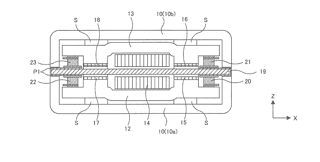
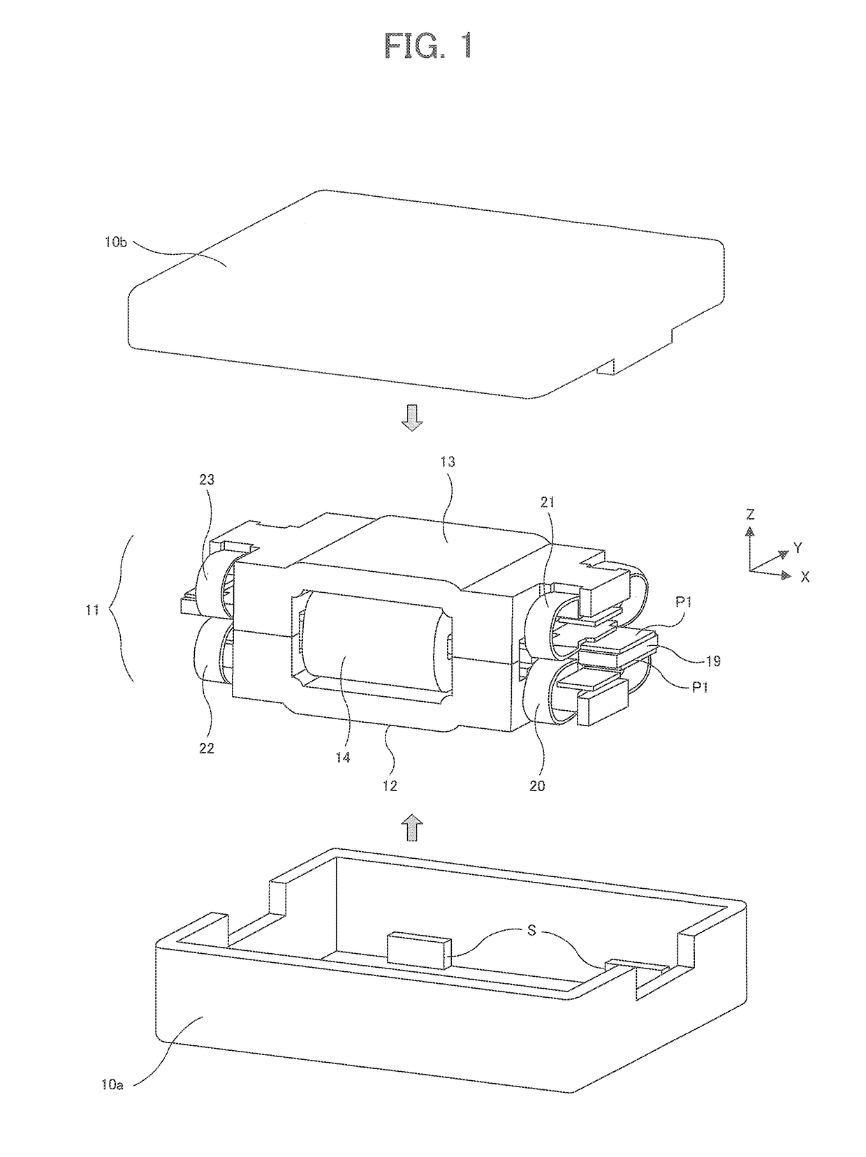
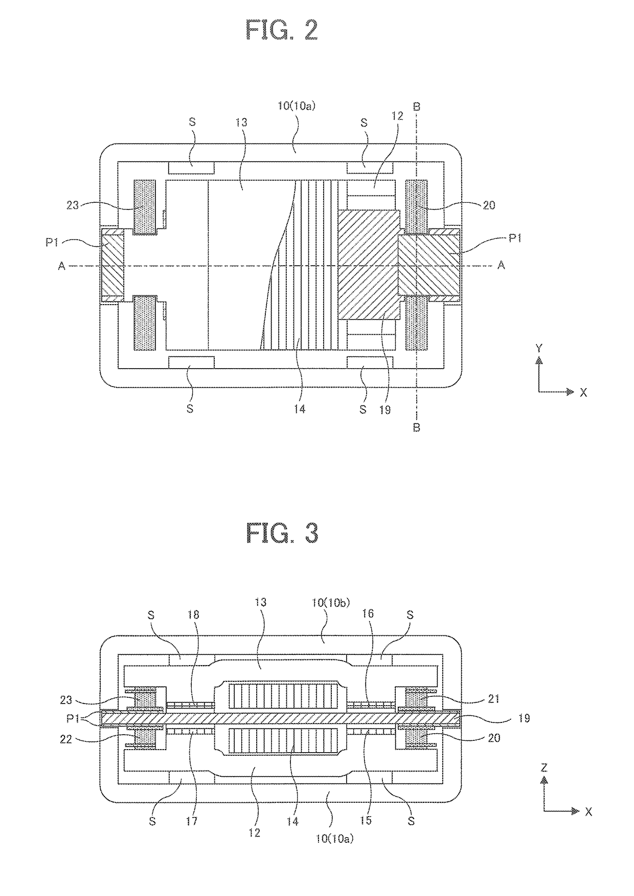
[0025]A basic structure of an electromechanical transducer of an embodiment will be described with reference to FIGS. 1 to 5. FIG. 1 is a perspective view showing a structure in which a housing 10 that contains the entire electromechanical transducer of the embodiment is detached. FIGS. 2 to 4 are views of the electromechanical transducer of the embodiment as viewed in directions perpendicular to one another, in which an X direction, a Y direction and a Z direction are indicated by arrows, respectively, for purposes of illustration. FIG. 2 i...


PUM


Abstract

An electromechanical transducer of the invention comprises a structural unit, an armature, and the first and second elastic units. The structural unit includes magnets, a yoke and a coil. The armature includes an inner portion disposed to pass through inside the structural unit and two outer portions protruding from the inner portion in a first direction, and the armature constitutes a magnetic circuit with the structural unit via two regions through which components of the magnetic flux flow in reverse directions in the inner region. The elastic units give restoring forces to the outer portions in response to displacement of the armature due to magnetic forces of the magnetic circuit. In the armature, a cross-sectional area at a predetermined position between the two regions is smaller than that at the two regions, and magnetic flux flowing in the first direction within a range of displacement of the armature.

Description

BACKGROUND OF THE INVENTIONField of the Invention[0001]The present invention relates to an electromechanical transducer that transduces an electric signal into mechanical vibration, and particularly relates to an electromechanical transducer that comprises a driving unit including an armature, a yoke, a coil, magnets and any other member.[0002]Description of Related Art[0003]An electromechanical transducer or an electroacoustic transducer used in a hearing aid or the like is provided with a driving unit including an armature, a yoke, a coil and magnets, etc., and is configured to drive the armature in response to an electric signal supplied to the coil so that relative vibration between the armature and other members is transduced into mechanical vibration or sound. For example, as examples of a so-called balanced armature type (hereinafter, referred to as “balanced type”) electromagnetic transducer, Patent Reference 1 discloses a structural example of a magnetic circuit using a U-s...

Claims


Application Information

Patent Timeline
Patent Type & Authority Applications(United States)
IPC IPC(8): H02K33/02
CPCH02K33/02H04R11/02H04R25/00
Inventor IWAKURA, TAKASHI
Owner RION COMPANY
Why Eureka
Try Eureka