Method of diffusion bonding of nickel based superalloy substrates

a superalloy and substrate technology, applied in the field of joining substrates, can solve the problems of affecting the quality of substrates, and requiring significantly more time for diffusion bonding than brazing, so as to improve the grain structure, improve the mechanical properties, and improve the effect of thinking uniformity

Inactive Publication Date: 2006-12-21
SIEMENS POWER GENERATION
View PDF8 Cites 9 Cited by
  • Summary
  • Abstract
  • Description
  • Claims
  • Application Information

AI Technical Summary

Benefits of technology

[0010] The use of electroless nickel plating to apply the interlayer results in bonds that have an interlayer with a more even thickness, a better grain structure, and better mechanical properties than traditional diffusion bonding.
[0011] Accordingly, it is an object of the present invention provide an interlayer in a diffusion bonding process that has a more uniform thinkness than other interlayers, and that is alloyed with an element that will lower its melting point and thereby improve surface-to-surface contact within the bond, and the strength of the resulting bond.
[0012] It is another object of the invention to provide improved surface to surface contact between the substrates and interlayer for a given surface roughness, thereby improving the mechanical properties of a bond.
[0013] It is a further object of the invention to provide a method of joining substrates together that is both economical and which produces stronger bonds than previous joining methods.
[0015] It is a further object of the invention to reduce the need for extensive processing to reduce the surface roughness of the substrates to be joined.

Problems solved by technology

Although brazing may be done quickly and economically, and produces a relatively strong joint, the joints produced by brazing are not as strong as the joints produced by other joining methods, and can be damaged by heat.
Diffusion bonding requires significantly more time than brazing to perform.
Surface roughness prevents ideal contact between substrates to be joined, thereby decreasing the mechanical properties of the joint.
Although some of the problem may be overcome by adding pressure to force contact between the substrates, acceptable pressure levels are limited by the deformation limits of the substrates, and the mechanical properties of the joints have still been found to vary.

Method used


Image

  • Method of diffusion bonding of nickel based superalloy substrates
  • Method of diffusion bonding of nickel based superalloy substrates
  • Method of diffusion bonding of nickel based superalloy substrates

Examples


Embodiment Construction

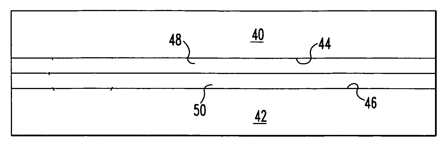
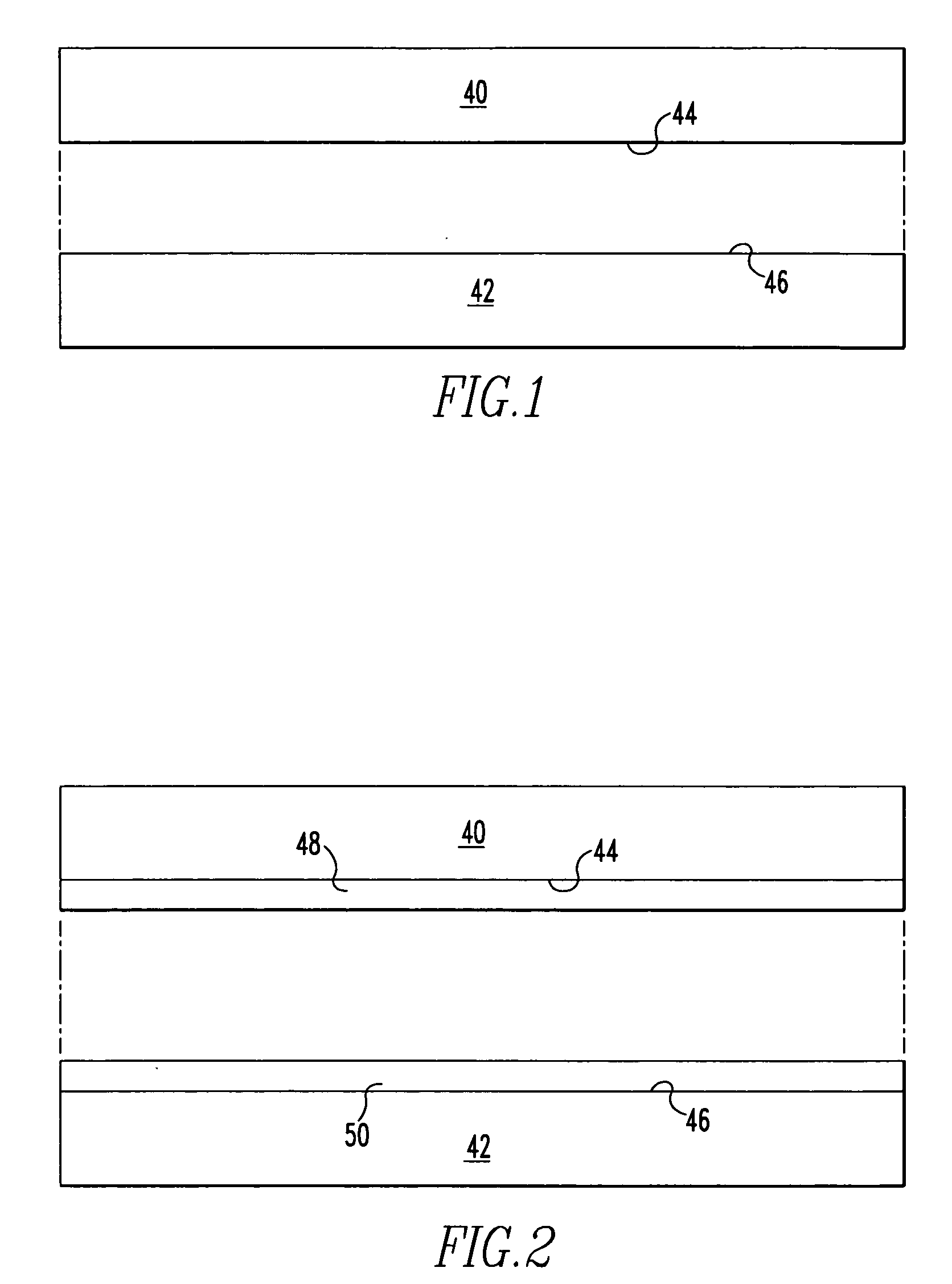
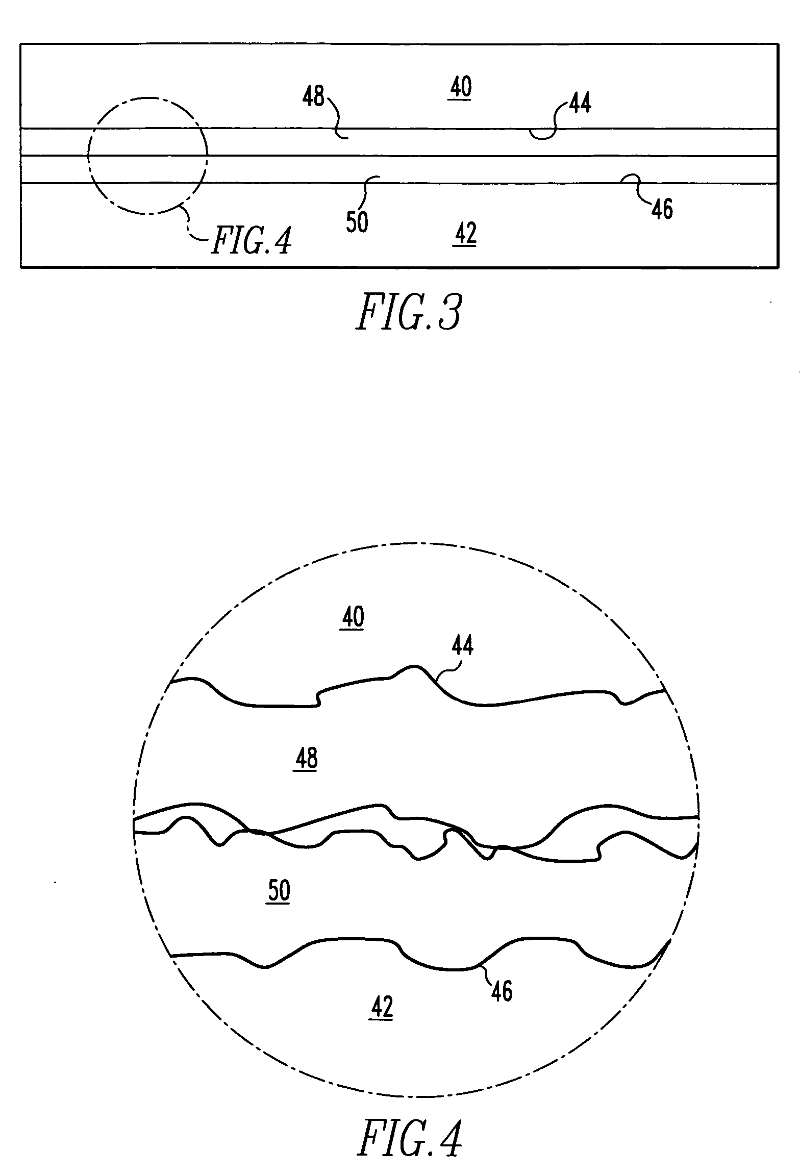
[0025] The present invention provides a method of joining a pair of substrates having improved surface to surface contact between the substrates and an interlayer between the substrates. The method provides for an interlayer that is applied to the joining surfaces in a manner resulting in a more uniform thickness.

[0026] Referring to FIGS. 1-7, the method of joining substrates is illustrated. The substrates 40, 42 shown in FIG. 1 may in some preferred embodiments be high nickel steel, for example, Inconel Alloy 617 or other Inconel alloys, or other similar materials. These alloys may also include solid solution strengthened alloys, or gamma prime alloys. Initially, the surfaces 44, 46 of the substrates 40, 42 will be sanded and / or polished to minimize their surface roughness. In some preferred embodiments, the average roughness (Ra) should not exceed about 30 μin., which will provide sufficient surface roughness for good adhesion of an electroless nickel plating while also providing...


PUM

PropertyMeasurementUnit
thicknessaaaaaaaaaa
pressureaaaaaaaaaa
temperatureaaaaaaaaaa

Abstract

A method of transient liquid phase bonding includes the use of an interlayer between the two substrates to be bonded that is alloyed with a melting point reducing element. The interlayer forms a liquid during the bonding process, resulting in superior surface contact between the interlayer and substrates during the bonding process. As the melting point decreaser diffuses out of the interlayer, the interlayer resolidifies, at which point bonding continues under the principles of diffusion bonding.

Description

BACKGROUND OF THE INVENTION [0001] 1. Field of the Invention [0002] The present invention relates to joining substrates together to form laminated structures. More specifically, the invention provides a method of diffusion bonding of substrates into laminated structures. [0003] 2. Description of the Related Art [0004] Substrates made from materials such as high nickel steels are presently joined into laminated structures by techniques such as brazing and diffusion bonding. [0005] Brazing is a means of joining metals with a filler metal therebetween, with the filler metal having a melting point substantially below that of the metals to be joined. The joint is formed by heating the metals above the melting point of the filler metal, but below the melting point of the substrates. Typical filler metals include copper, copper alloys, silver, silver alloys, and aluminum alloys. Although brazing may be done quickly and economically, and produces a relatively strong joint, the joints produc...

Claims


Application Information

Patent Timeline
Patent Type & Authority Applications(United States)
IPC IPC(8): B23K35/12B23K20/00
CPCB23K20/028B23K2203/08B23K20/16B23K2103/02B23K2103/26
Inventor CIONA, STEVEDER WEG, PAUL VANPRYCE, STEVEABRAHAM, BARRIECASTILLO, RAFAEL
Owner SIEMENS POWER GENERATION
Why Eureka
Try Eureka