Inducing heating device for thin steel strip coil and heat treatment process thereof
A technology of induction heating device and induction heating coil, which is applied in the field of heating device and its heat treatment process, can solve the problems of incapable of heat treatment of thin steel plate, inability of thin steel coil to eliminate residual internal stress of annealed products, and lack of heat treatment of thin steel coil, etc. Achieve the effects of saving energy and time, good brightness, simple and practical process
- Summary
- Abstract
- Description
- Claims
- Application Information
AI Technical Summary
Problems solved by technology
Method used
Image
Examples
Embodiment 1
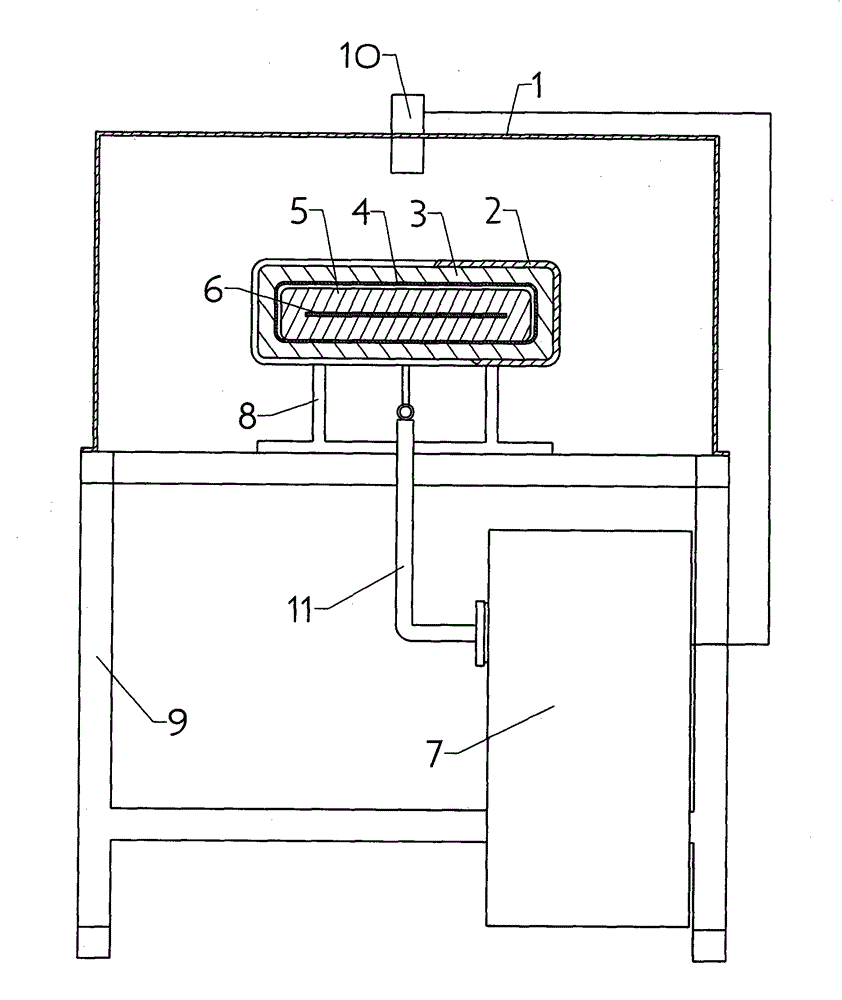
[0036] As shown in the figure, an induction heating device for a thin steel strip coil is composed of: an induction heating device furnace shell 1, an induction heating coil 2, a high temperature resistant fiber insulation furnace lining 3, a quartz tube 4, a graphite furnace lining 5, and a graphite inner cavity 6 , a power supply device 7, a support 8, a base 9, a temperature measuring device 10, and a water-cooled cable device 11; a base 9 is provided below the furnace shell 1 of the induction heating device, and a support 8 is provided in the middle of the top of the base 9; a rectangular induction heating device is provided on the support 8 The heating coil 2 is in the furnace shell 1 of the induction heating device, and the induction heating coil 2 is provided with a high-temperature-resistant fiber insulation furnace lining 3 with a rectangular cross-section. Graphite furnace lining 5, a rectangular graphite inner chamber 6 is reserved in the middle of the graphite furna...
Embodiment 2
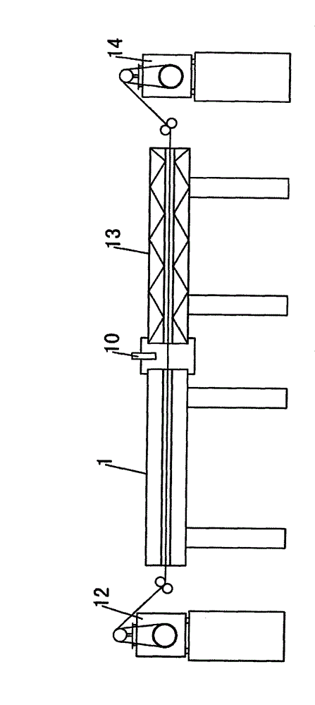
[0044] As shown in the figure, a heat treatment process of an induction heating device for a thin steel strip coil, the specific process steps are as follows: first, run the uncoiler 12 and the coiler 14 to make the uncoiler 12 and the coiler 14 work synchronously ; The thin steel strip coil is uncoiled by the uncoiler 12 to become a thin steel strip with a cross-sectional tension ≤ 1MPa, which is sent into the induction heating device;
[0045] At this time, the power supply device 7 of 750KW kilowatts, 5KHZ kilohertz-10KHZ kilohertz is used to supply power to the induction heating coil 2. After the induction heating coil 2 is connected to the power supply, the high temperature resistant fiber insulation furnace lining 3 with a thickness of 8 mm produces a magnetic field. The graphite furnace lining 5 generates a current of 30A-200A ampere, so that the graphite furnace lining 5 is evenly heated, and the heating temperature reaches 1050°C-1700°C; at the same time, the protectiv...
Embodiment 3
[0051] As shown in the figure, a heat treatment process of an induction heating device for a thin steel strip coil, the specific process steps are as follows: first, run the uncoiler 12 and the coiler 14 to make the uncoiler 12 and the coiler 14 work synchronously ; The thin steel strip coil is uncoiled by the uncoiler 12 to become a thin steel strip with a cross-sectional tension ≤ 1MPa, which is sent into the induction heating device;
[0052] At this time, use 750KW kilowatts, 5KHZ kilohertz power supply device 7 to supply power to the induction heating coil 2, when the induction heating coil 2 is connected to the power supply, a magnetic field is generated through the 8 mm thick high temperature resistant fiber insulation furnace lining 3, inside the graphite furnace lining 5 Generate a current of 30A ampere, so that the graphite furnace lining 5 is evenly heated, and the heating temperature reaches 1050°C; at the same time, a protective gas ammonia decomposition gas is int...
PUM
| Property | Measurement | Unit |
|---|---|---|
| thickness | aaaaa | aaaaa |
Abstract
Description
Claims
Application Information
 - R&D
- Intellectual Property
- Life Sciences
- Materials
- Tech Scout
- Unparalleled Data Quality
- Higher Quality Content
- 60% Fewer Hallucinations
Browse by: Latest US Patents, China's latest patents, Technical Efficacy Thesaurus, Application Domain, Technology Topic, Popular Technical Reports.
© 2025 PatSnap. All rights reserved.Legal|Privacy policy|Modern Slavery Act Transparency Statement|Sitemap|About US| Contact US: help@patsnap.com


