Multinary deposition film production stabilizing device and method, and tool with multinary deposition film

Inactive Publication Date: 2006-12-14
NACHI-FUJIKOSHI
View PDF1 Cites 0 Cited by
  • Summary
  • Abstract
  • Description
  • Claims
  • Application Information

AI Technical Summary

Benefits of technology

[0013] Accordingly, it is desired to form a multicomponent film containing metal components such as TiAlN having greatly different melting points in adequate quality, for instance, in which each component of different metals is distributed at a desired rate over the whole film thickness. It is also preferable to form the film at high material use efficiency by using a raw material alloy which has metal components not required to be strictly matched with an objective film composition but almost close to the objective film composition, and of which the whole part can be effectively used.
[0019] As a result, it is possible to form a film in adequate quality, in which respective metal components with greatly different melting points of a metal such as TiAlN form a desired composition distribution over the whole film thickness by controlling the composition of a starting raw material and the melting rate of an unmelted portion. The vaporizing raw material does not need to be strictly matched with an objective film composition and may be an alloy having a metal composition approximately close to the objective film composition.
[0021] With the use of the sintered compact or the green compact, a melted portion can be separated from an unmelted portion. The raw material can be therefore effectively used almost in entirety with the unmelted portion sequentially melted and evaporated, and the material use efficiency is high.
[0050] As is apparent from Table 1, the high speed steel drill with the hard film according to the invention shows the very long life almost twice as compared with the conventional examples. This is because the melting method forms almost no droplet and imparts small surface roughness.
[0051] According to the invention, the multicomponent film containing metal components with greatly different melting points such as TiAlN had such adequate film quality as to show the desired distribution of the respective, different metal components over the whole film thickness. Further, as for the vaporizing raw material, since it does not need to strictly match with the objective film composition, a raw alloy material having metal compounds approximately close to the objective film composition may be used and almost the whole parts of the material can be effectively used so that the material use efficiency is high.
[0053] When the sintered compact or the green compact is used as the starting raw material, the raw material is increased in apparent volume by heat and forms vacant gaps inside the sintered compact or green compact. The sintered compact or the green compact having the vacant gaps has a higher heat-insulating effect as compared with an alloy material and decreases the volume after having been melted. This allows the melted portion and the unmelted portion to be easily separated. EXAMPLE 2

Problems solved by technology

However, these methods need an expensive alloy target serving as a vaporizing material and need to prepare the target of a composition according to an objective film composition.
Further, the methods hardly use the whole of a raw material, by reason of an electromagnetic field and a holding method of the target.
In addition, the arc process inevitably involves deposition of unreacted metal droplets and can not form a film with satisfactory quality.
However, the conventional melting method has difficulty in uniformly evaporating two or more sorts of metal materials with remarkably different melting points.
Thus, the film containing two or more sorts of metal elements formed with the conventional method has a distributed composition wholly depending on their melting points, and accordingly has had difficulty in controlling the composition distribution in a film thickness direction.
However, a melted portion overlies the unmelted portion, and a complicated control unit is required for moving the melted portion.
Further, In addition, a film-forming rate by the melting method depends on a distance or positional relation of the evaporation source from or with an article to be vapor-deposited, but it is difficult for the apparatus having the plurality of evaporation sources to uniformize the positional relationship between the plurality of evaporation sources and the article to be vapor-deposited.
For this reason, it is almost impossible to obtain a film having a consistent composition.

Method used


Image

  • Multinary deposition film production stabilizing device and method, and tool with multinary deposition film
  • Multinary deposition film production stabilizing device and method, and tool with multinary deposition film
  • Multinary deposition film production stabilizing device and method, and tool with multinary deposition film

Examples


example 1

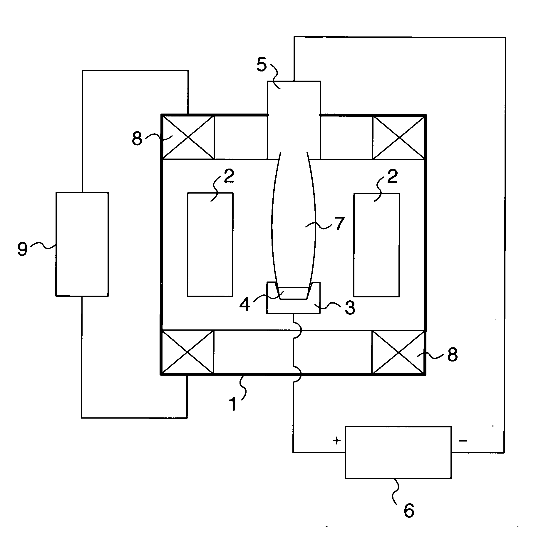
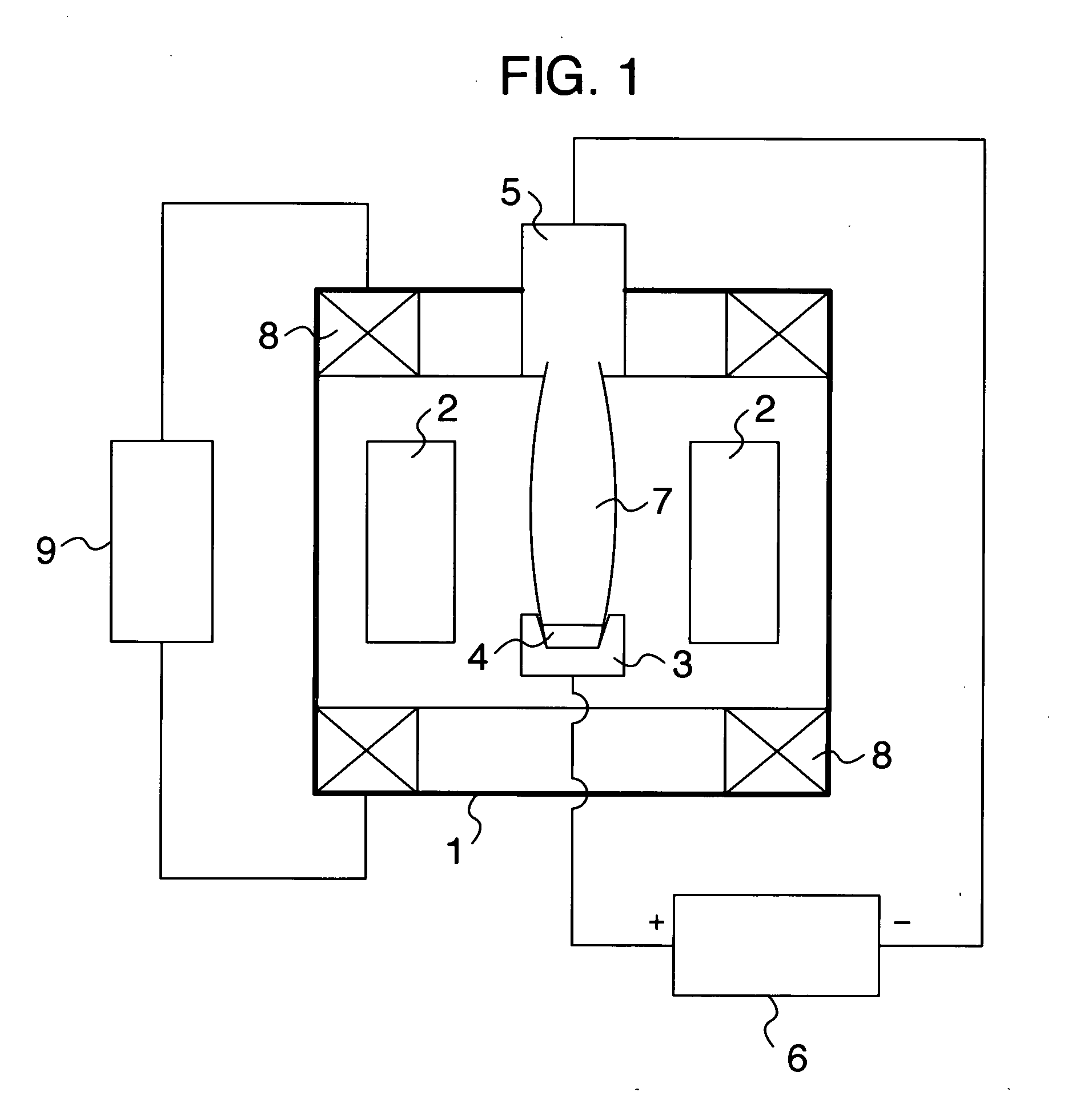
[0039] A vaporizing raw material was prepared by die-molding 30 g of a mixed powder of Ti and Al having metal components approximately close to an objective film composition into a tubular shape having a diameter of 40 mm, with the force of 2 GPa. The green compact was charged into the crucible (or hearth), the workpiece was heated and cleaned, and then, the green compact was melted and evaporated in a mixture atmosphere of argon and nitrogen gases at a pressure of about 1 Pa. At this time, a HCD gun was used, which was set to converge the diameter of a plasma beam into about 10 mm on the top face of the green compact, and a plasma output was increased by 500 W per minute up to 8,000 W.

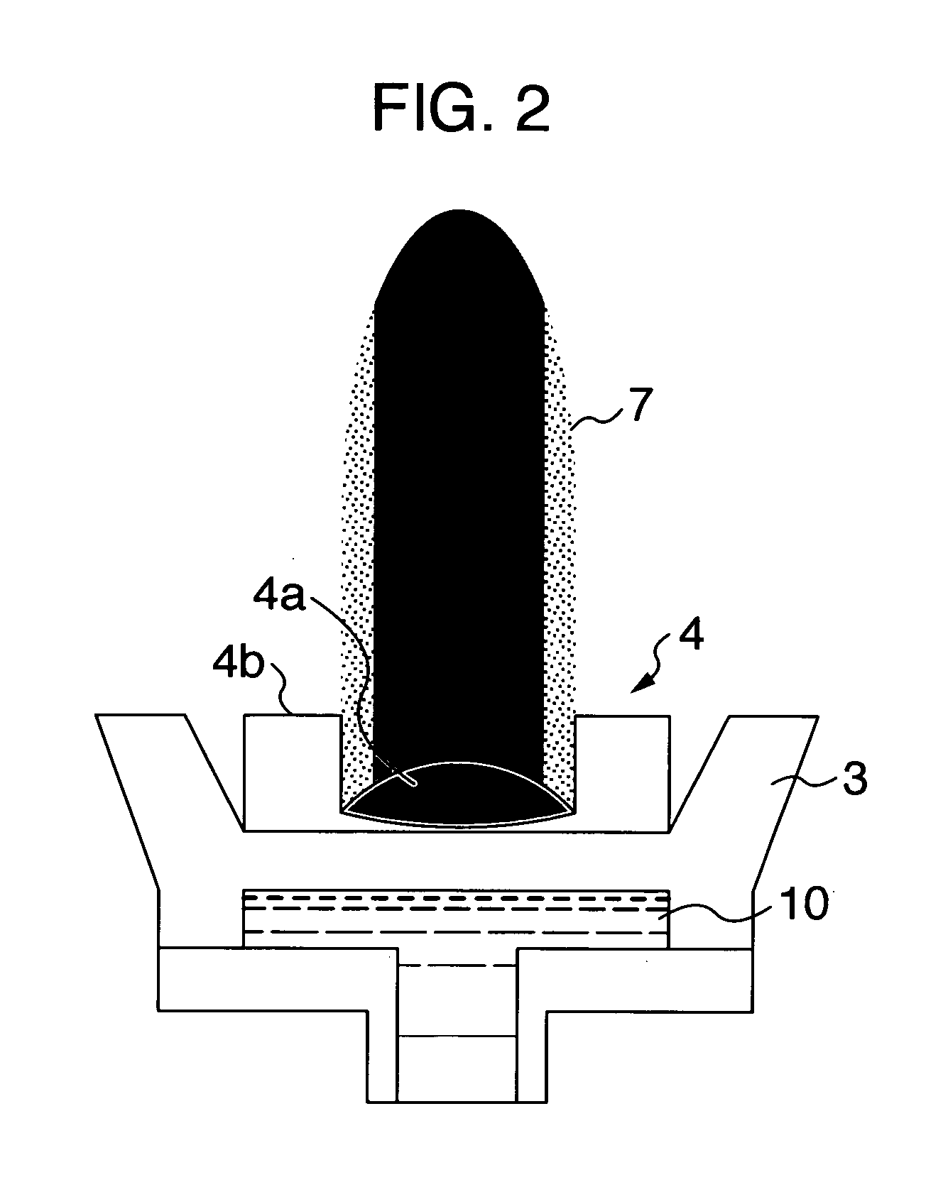
[0040] At the same time, the plasma control was performed so as to continuously and sequentially move and expand the diameter of the plasma beam from the region of the 10 mm diameter about the approximate center of the green compact so as to finally cover almost the entire green compact of the 40 mm ...

example 2

[0054] Cemented carbide inserts (A30) were coated under the condition of Example 1 and were heated to and held at 900° C. for one hour in atmospheric air. The result of measuring the thicknesses of surface oxide layers of the inserts is jointly written in Table 1 (item name: oxidization thickness). It is understood that since the film has less film defects such as droplets as compared with that according to the arc process (the conventional example), progression of oxidation is slow and the thickness of an oxidized layer is small (improves oxidation resistance).

example 3

[0055] A cemented carbide end mill previously coated with a TiCN film in the condition of Example 1 was coated with a TiAlN film. A wear width in the flank of the cemented carbide end mill was measured after it had cut the length of 60 m, and the result is written together in Table 1 (item name: end mill flank wear). Cutting conditions are shown below.

[0056] (Cutting Condition of Cemented Carbide End Mill)

[0057] tool: φ10 cemented carbide square end mill with two cutting edges

[0058] cutting method: downward side cutting

[0059] work material: SKD61 (hardness 53 HRC)

[0060] depth of cut: 10 mm in axial direction and 0.2 mm in diametrical direction

[0061] cutting speed: 314 m / min, feed: 0.07 mm / edge

[0062] cut length: 60 m, lubricant: none (air blow)

[0063] The cemented carbide end mill showed abrasion resistance equal to or slightly better than the TiAlN film formed by the arc process. Because the films have the same content, it is considered that the improvement of the oxidation r...


PUM

PropertyMeasurementUnit
Poweraaaaaaaaaa
Areaaaaaaaaaaa
Melting pointaaaaaaaaaa

Abstract

A production stabilizing device and a method produce a multicomponent film containing metal components such as TiAlN having greatly different melting points at high material use efficiency and in a good film quality by using a single crucible (3) and converged plasma (7). For this end, electric power required to evaporate material (4) is first supplied and then electric power stepwise increased from the first electric power is repeatedly supplied until a required maximum electric power is reached. Alternatively, plasma control is performed for converging the plasma (7) into an initial area required to evaporate the material and subsequently plasma control is performed for successively and stepwise moving and expanding the plasma from the initial plasma area up to a maximum plasma area to gradually melt a non-melted portion (4b) of the material. The material is a sintered compact or a green compact (4).

Description

TECHNICAL FIELD [0001] The present invention relates to production stabilizing device and method which can more easily produce a nitride, a carbide, a boride, an oxide or a silicide containing two or more metal components such as TiAlN than prior art, and relates to a coated tool with a film formed by the method. BACKGROUND ART [0002] A PVD (Physical Vapor Deposition) method has been known as a method of coating a product surface to give it abrasion resistance, oxidation resistance, corrosion resistance and other some functions. [0003] An ion plating method, which is used as one of the PVD method and combines one part of a vacuum deposition method with a sputtering process, is a surface treatment method for forming a coating of a metal compound such as a metal carbide, a metal nitride and a metal oxide or a compound thereof. This method is now significant as the method of coating particularly the surface of a sliding member and a cutting tool. [0004] Conventionally, a nitride contai...

Claims


Application Information

Patent Timeline
IPC IPC(8): C23C16/00H05B6/00B23B27/14B23B51/00B23P15/28C23C14/06C23C14/32
CPCC23C14/32C23C14/0641B23B27/14B23B51/00B23P15/28C23C14/24
Inventor SATO, HIDEKISONOBE, MASARUKATO, NORIHIROYASUOKA, MANABU
Owner NACHI-FUJIKOSHI
Why Eureka
Try Eureka