
Ammonia oxidation catalyst for the coal fired utilities

a technology of ammonia oxidation and coal-fired utilities, which is applied in the direction of physical/chemical process catalysts, metal/metal-oxide/metal-hydroxide catalysts, and separation processes, etc., can solve the problem of ammonia gas emission into the atmosphere, ammonia slip, and ammonia gas affecting downstream components and processes, so as to reduce the ammonia content

Inactive Publication Date: 2006-08-17
BASF CATALYSTS LLC
View PDF21 Cites 50 Cited by
  • Summary
  • Abstract
  • Description
  • Claims
  • Application Information

AI Technical Summary

Benefits of technology

[0027] One aspect of the present invention is to provide a commercially viable process that reduces the ammonia concentration to levels that will not contaminate the fly ash from coal-fired plants and will additionally reduce the present undesirable emissions level of ammonia in both coal-fired plants and plants that use other hydrocarbon fuels.
[0028] Another aspect of the present invention is to provide oxidation of both ammonia and carbon monoxide, while maintaining relatively no sulfur dioxide oxidation.

Problems solved by technology

The discharge of all of these contaminates into the atmosphere is subject to federal and local regulations, which greatly restrict the levels of these flue gas components.
One common problem with the SCR and SNCR technologies is that some residual ammonia, known as ammonia slip, negatively impacts downstream components and processes such as: air pre-heater fouling, fly ash contamination, and ammonia gas emission into the atmosphere.
The ammonia slip problem is further exacerbated as the result of SCR catalyst surface deterioration as well as misdistribution in flue gas velocity, temperature, and concentrations of ammonia and NOx.
An additional problem with the current methods is that increased ammonia injections will more efficiently remove the oxides of nitrogen, but then the excess ammonia will result in increased ammonia slip in the flue gas.
In coal-fired power plants this excess ammonia can, in addition, contaminate the resulting coal based fly ash.
Even in power plants that are based on natural gas or oil, the environmental effects of the exhausted ammonia is undesirable.
(3) large ammonia consumption.
Thus, the nitrogen oxide separation efficiency of the known processes is limited by the amount of unreacted ammonia that can be discharged into the atmosphere.
Besides, variation in the load on the combustion equipment will change the temperature, at the point where ammonia is introduced, to a value deviated from the optimum temperature range, and this in turn will decrease the decomposition rate, tending to increase the proportion of residual ammonia.
This product will stick to the rear heat-transfer surface in the relatively low-temperature region, for example, to the heating surfaces of the air preheater and associated parts of a boiler, causing an increase in pressure loss, hampering the operation of the combustion equipment, and attacking the materials of the equipment for their eventual corrosion.
As described above, the ammonia left unremoved in the treated exhaust gas provides a major obstacle in the way to practical operation.
Consequently, there is an upper limit to the ammonia supply and naturally the NOx decomposition rate is low.
This has been a problem in the practice of high-temperature noncatalytic denitrification.
Furthermore, ammonia, which is introduced in the high-temperature region, undergoes a concomitant reaction for decomposing itself, resulting in the disadvantage (3) of excess consumption of ammonia, or more than the equivalent for the NOx-decomposing reaction.
This has been another limiting factor for the rate of NOx decomposition to be attained conventionally.
Furthermore, depending upon the temperature at the cold end of the air preheater, excess ammonia slip may cause clogging of the space between adjacent air preheater heating elements because of the formation of ammonium sulfate / bisulfate, and / or agglomerated fly ash.
This results in increased pressure loss of the heat exchanger, corrosion of the apparatus, and therefore unstable operation for a prolonged period and other disadvantages.
While it is believed that the ammonia that evolves has no measurable effect on concrete quality (strength, permeability, etc.), the ammonia gas can range from mildly unpleasant to a potential health hazard.
Ammonia gas concentration between 150 and 200 ppm can create a general discomfort.
At concentrations between 400 and 700 ppm, ammonia gas can cause pronounced irritation.
At 500 ppm, ammonia gas is immediately dangerous to health.
Other than OSHA exposure limits, there are no current regulatory, industry or ASTM standards or guidelines for acceptable levels of ammonia in fly ash.
Depending on site and weather conditions, fly ash with ammonia concentration ranging between 100 and 200 mg / kg may result in unpleasant or unsafe concrete placement and finishing work environment.
Fly ash with ammonia concentration exceeding 200 mg / kg would produce unacceptable odor when used in Ready-Mixed concrete applications.
In addition to the risk of human exposure to ammonia gas evolving from concrete produced using ammonia laden ash, the disposal of ammonia laden ash in landfills and ponds at coal burning power stations could also create potential risks to humans and the environment.
Upon contact with water, the ammonium salts leach into the water and could be carried to ground water and nearby rivers and streams causing potential environmental damage such as ground water contamination, fish kill and eutrophication.
Water conditioning and wet disposal of alkaline fly ashes would expose power plant workers to ammonia gas.
However, when the quantity of ammonia used is high enough to effectively remove the NOx through SCR, some of the excess ammonia will go through the catalyst unchanged and exit as ammonia slip in the flue gases creating the problem of a toxic reactive gas in the exiting gases.
Another major problem created by the excess ammonia exiting in the flue gases, particularly from coal-fired plants, is that the ammonia contaminates the fly ash that is intended for use in mixtures with cement to make concrete.

Method used


Image

  • Ammonia oxidation catalyst for the coal fired utilities
  • Ammonia oxidation catalyst for the coal fired utilities
  • Ammonia oxidation catalyst for the coal fired utilities

Examples


example 1

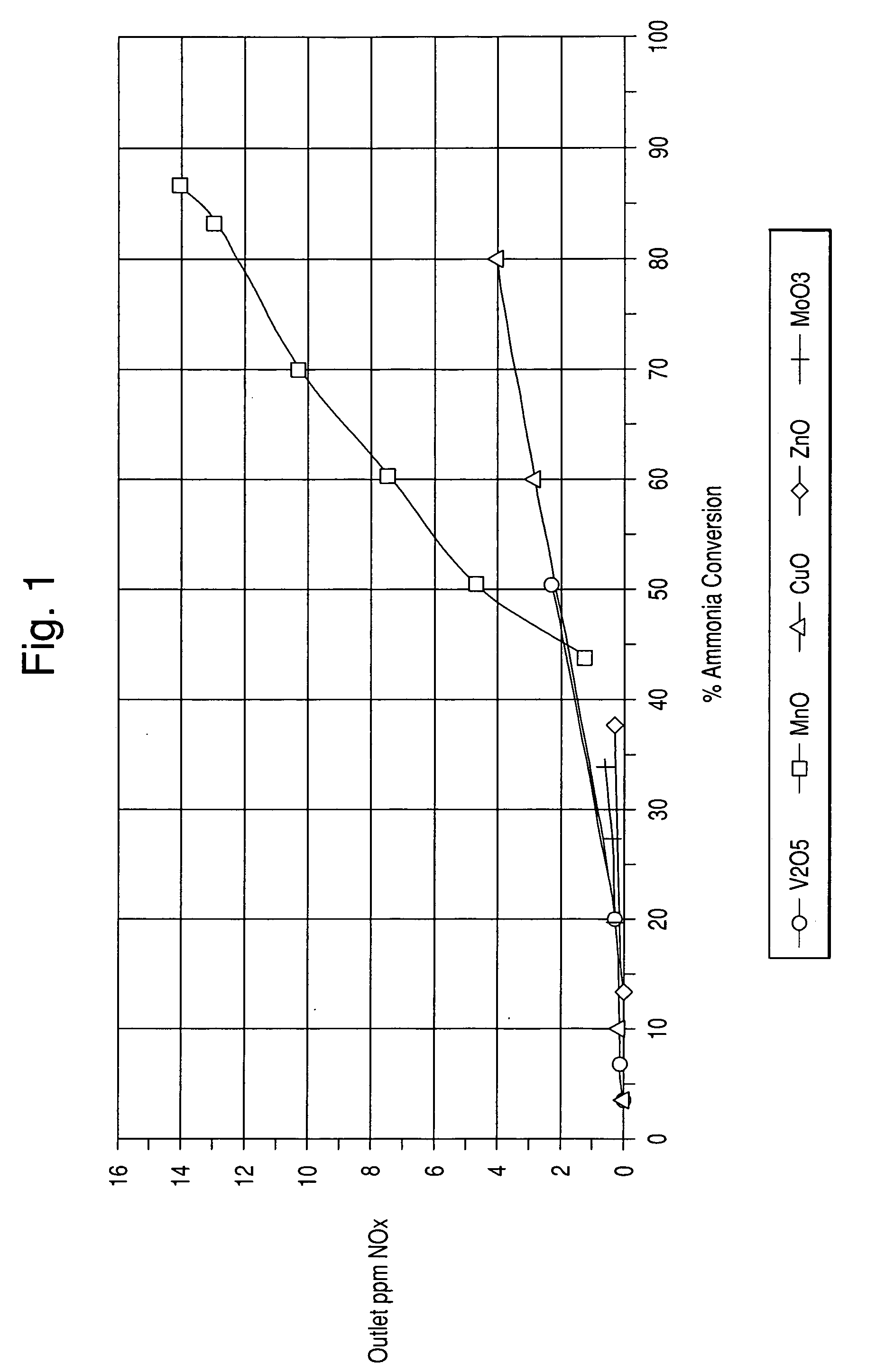
[0054] In this example, sample catalysts comprising various metal oxides impregnated onto a titania support of about 90 m2 / g surface area were prepared. The metal oxides were V2O5, MnO, CuO, ZnO, and MoO3.

[0055] Preparation of the vanadium / titania catalyst was performed as follows: [0056] 1. A 13 wt. % Vanadyl Oxalate solution in water was further diluted with 7.28 g of water [0057] 2. 193.7 g of titania from Millenium were impregnated with 142.86 g of the Vanadyl Oxalate solution [0058] 3. The impregnated titania powder was dried and calcined at 400° C. for 2 hours

[0059] All other metal oxide catalysts were prepared with the same procedure as above. Table 1 below sets forth the weights of the materials.

TABLE 1Ti02 (g)H2O (g)Ammonium Heptamolybdate tetrahydrate (25.49 g)193.68125.37Zinc sulfate heptahydrate (57.11 g)193.68106.4Manganese Nitrate (80.72 g)193.6883.02Copper sulfate heptahydrate (51.25 g)193.6893.77

example 2

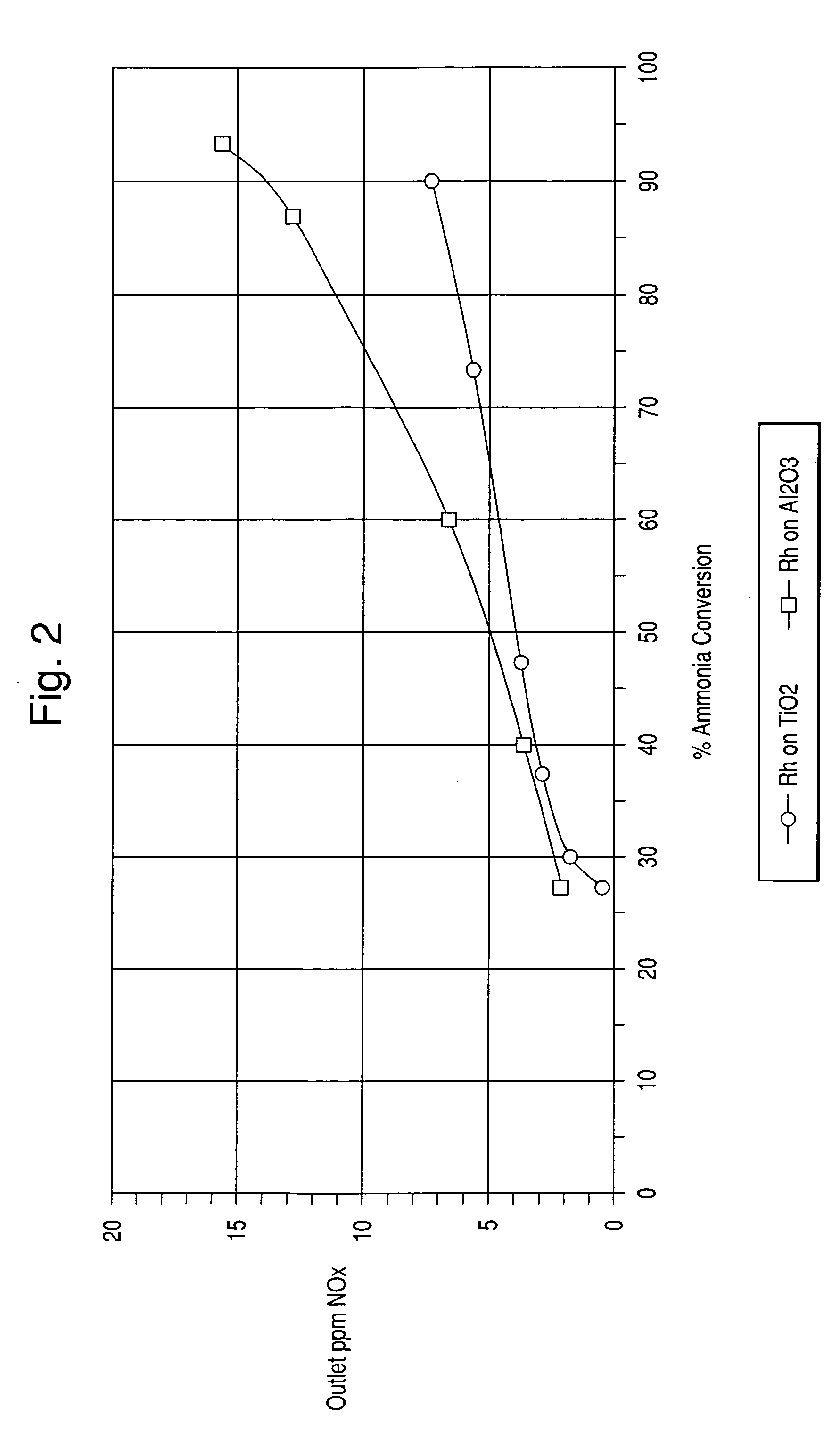
[0060] In this example, catalysts comprising precious metal on titania and precious metal on alumina were prepared.

[0061] The titania support used herein was that of Example 1. The alumina support comprised SBA150 from Alcoa. The alumina support had a surface area of about 150 m2 / g.

[0062] 1.89 g of an 18.2% Pt“A” solution (Dihydrogen hexahydroxyplatinate (IV) dissolved in monoethanolamine) was diluted with 111.34 g of water. 205.84 g of titania was impregnated with the Pt solution. The powder was then dried and calcined at 400° C. for 2 hours. The other catalysts were prepared in the same manner. The amount of materials used are listed in Table 2 below.

TABLE 2Ti02 (g)H2O (g)Pt “A” (1.87 g)205.84111.34Palladium Nitrate (1.75 g)205.84111.46Rhodium Nitrate (1.75 g)205.84112.24Alumina (g)H2O (g)Pt “A” (1.87 g)201.68109.06Palladium Nitrate (1.75 g)201.68109.17Rhodium Nitrate (3.35 g)210.17112.24

example 3

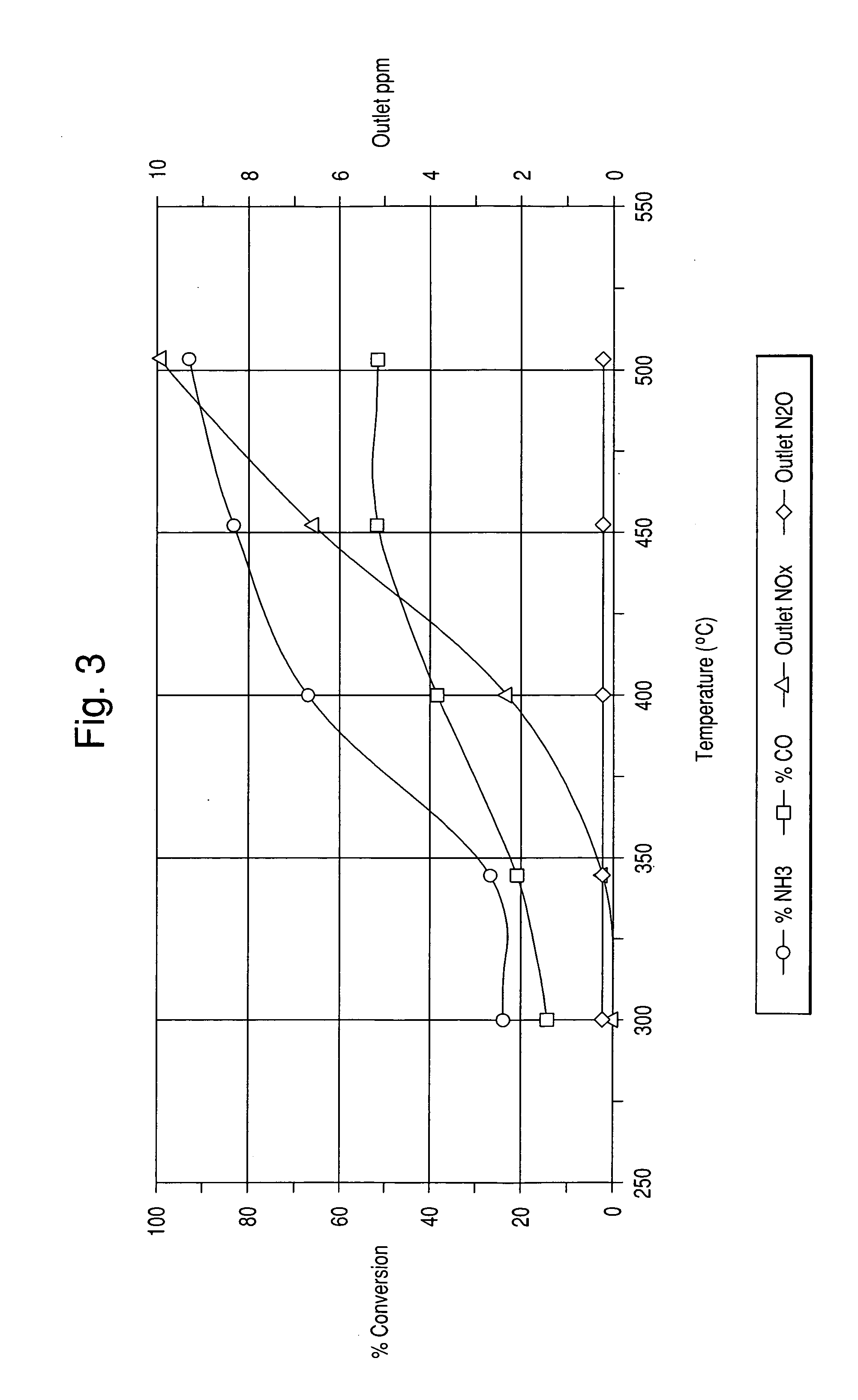
[0063] In this example, the preparations of honeycomb catalysts using the PM impregnated alumina powder of Example 2 are described.

[0064] A slurry was prepared by ball milling 41 g of each of the PM impregnated alumina powders prepared in Example 2, 49 g of water and 10 g of acetic acid to a particle size of 10 microns or less. A 64 cpsi honeycomb was then coated with the slurry to 1.7 g / in3 loading after calcining. The coated honeycomb was then dried and calcined at 500° C. for 1 hour.


PUM

PropertyMeasurementUnit
temperaturesaaaaaaaaaa
wt. %aaaaaaaaaa
wt. %aaaaaaaaaa

Abstract

A process is described that removes by oxidation the excess ammonia (NH3) gas from flue gases that have been subjected to selective catalytic reduction (SCR) of oxides of nitrogen (NOx) by ammonia injection. The inventive process incorporates a secondary catalyst of precious metal and vanadia on a metal oxide such as titania to catalyze the oxidation of both ammonia and carbon monoxide (CO) while maintaining sulfur dioxide (SO2) levels.

Description

FIELD OF THE INVENTION [0001] The present invention is directed towards a process that removes by catalytic oxidation the excess ammonia (NH3) gas from flue gases that have been subjected to selective catalytic reduction (SCR) of oxides of nitrogen (NOx) by ammonia injection. The invention further relates to methods for the removal of residual ammonia from flue gases prior to deposition on fly ash. BACKGROUND OF THE INVENTION [0002] Much of the electrical power used in homes and businesses throughout the world is produced in power plants that burn a fossil fuel (i.e. coal, oil, or gas) in a boiler. The resulting hot exhaust gas (also sometimes termed “flue gas”) turns a gas turbine or boils water to produce steam, which turns a steam turbine, and the turbine cooperates with a generator to produce electrical power. The flue gas stream is subsequently passed through an air preheater, such as a rotating wheel heat exchanger that transfers heat from the flue gas to an incoming air strea...

Claims


Application Information

Patent Timeline
Patent Type & Authority Applications(United States)
IPC IPC(8): B01D53/56
CPCB01D53/8625B01D53/8634B01J21/063B01J23/8877B01J23/8993B01J37/0248B01D53/58B01D53/94
Inventor TRAN, PASCALINE HARRISONLAPADULA, GERARD DIOMEDELIU, XINSHENG
Owner BASF CATALYSTS LLC
Learn More