
Composition for controlled sustained release of a gas

a technology of controlled release and gas, which is applied in the direction of biocides, biocide, animal repellents, etc., to achieve the effects of rapid flow rate, short residence time, and high gas quantity

Inactive Publication Date: 2006-08-10
EI DU PONT DE NEMOURS & CO
View PDF23 Cites 19 Cited by
  • Summary
  • Abstract
  • Description
  • Claims
  • Application Information

AI Technical Summary

Benefits of technology

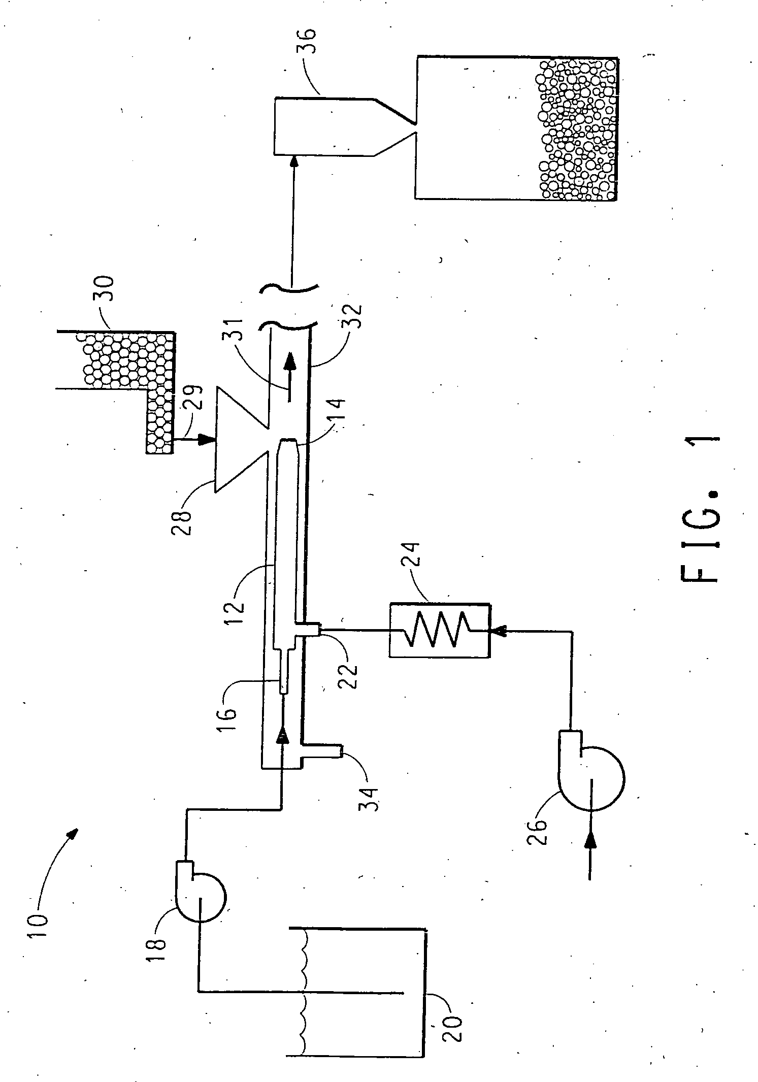
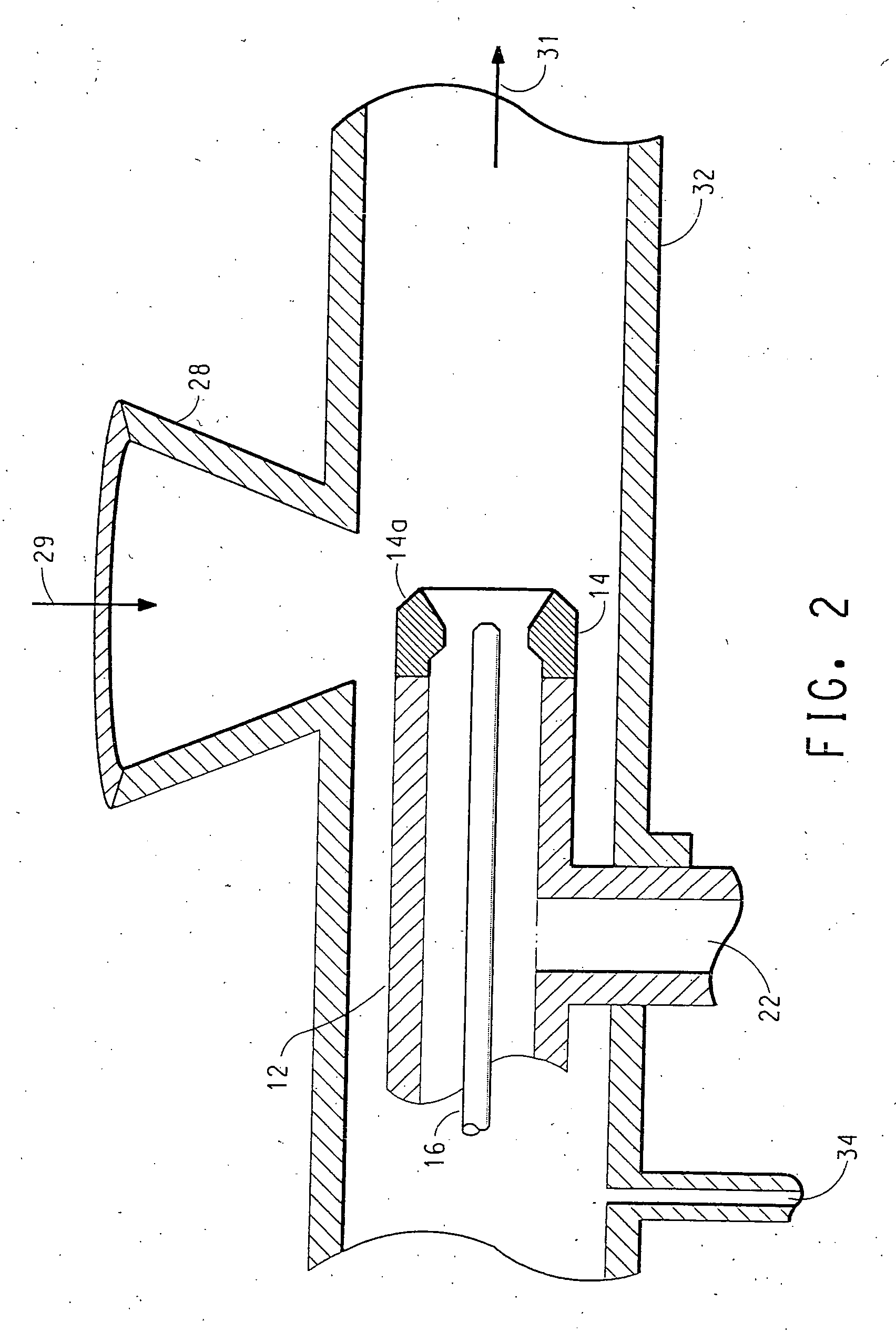
[0010] It has been found that mixing an energy-activated catalyst in a zone of turbulence with a source of anions capable of being oxidized by the activated catalyst or reacted with species generated during activation of the catalyst to generate a gas produces a composition which can generate higher quantities of gas than compositions formed by spray drying. The high temperatures and harsh conditions of this process do not appear to have a negative impact on a temperature sensitive source of anions such as sodium chlorite probably because of the short residence time and rapid flow rates.

Problems solved by technology

The high temperatures and harsh conditions of this process do not appear to have a negative impact on a temperature sensitive source of anions such as sodium chlorite probably because of the short residence time and rapid flow rates.

Method used


Image

  • Composition for controlled sustained release of a gas
  • Composition for controlled sustained release of a gas
  • Composition for controlled sustained release of a gas

Examples


example 1

[0118] A solution of sodium chlorite (NaClO2) was prepared by dissolving 30.0 parts technical grade (80% active) sodium chlorite in 70 parts high purity water (deionized and polished).

[0119] The solution was fed to an injector apparatus such as that shown in FIGS. 1 and 2 in order to treat titanium dioxide pigment particles R-101 sold by E. I. du Pont de Nemours and Company and Degussa P25. The titanium dioxide pigment was metered at a feed rate of 300 to 800 g / minute while the sodium chlorite solution feed rate was 50-250 g / minute. The gas stream was nitrogen which was injected through the flow restrictor at a pressure of 60 psig and the temperature of the gas stream was 325° C. The mean residence time in the zone of turbulence was about 1-2 milli-seconds.

[0120] The weight % amounts of sodium chlorite and chlorite ion based on the total weight of the catalyst and salt are shown in Table 1.

[0121] The gas stream was nitrogen which was injected through the flow restrictor at a pres...

example 2

[0122] A solution of sodium chlorite was prepared as described above. Dispersions of the titanium dioxide (R-101 and P25) in water were made at about 30-50 wt. % at pH 8-9 using 2-amino-2-methy-1-proparol to control pH. To this dispersion was added an amount of sodium chlorite solution and water to give about 18 wt. % titanium dioxide in water which was spray dried by atomization using nozzles at a temperature ranging from about 190 to about 220° C. The weight % amounts of sodium chlorite and chlorite ion based on the total weight of the catalyst and salt are shown in Table 2.

TABLE 2Spray DryerTiO2 Gradewt. % NaClO2wt. % ClO2−P255P2510R-10151.22R-101104.46

[0123] Comparing the data reported in Tables 1 and 2, it is apparent that the process of this invention for treating the titanium dioxide with the chlorite provides a composition with a higher concentration of chlorite ion as compared to spray drying. This is unexpected since spray drying uses lower temperatures and milder condit...

example 3

[0125] The energy activated catalysts of Table 3 were each treated with sodium chlorite following the procedure of Example 1 to produce treated samples.

[0126] The treated samples were exposed to ultra violet radiation using a 10 watt UV bulb at six 30-second intervals. The amount of ClO2 released was detected using an Interscan LD Series Model 33 ClO2 detector. The results are reported in Table 3.

TABLE 3ClO2 ppmSample30 sec.60 sec.90 sec.120 sec.150 sec.180 sec.TiO2 R-1012.96.28.510.010.811.5gradeZinc Oxide1.02.13.03.54.04.3Silicate Clay0.00.30.40.60.60.6

[0127] It is believed that silicate clay of this example which is considered to lack photoactivity produced a minor amount of ClO2 from direct photogeneration from the NaClO2.


PUM

PropertyMeasurementUnit
temperaturesaaaaaaaaaa
pressureaaaaaaaaaa
pressureaaaaaaaaaa

Abstract

The invention relates to an improved composition for generating at least one gas comprising an energy-activated catalyst capable of being activated by electromagnetic energy, heat and / or moisture and anions capable of being oxidized or reacted to generate at least one gas, the composition, when exposed to electromagnetic energy, heat and / or moisture being capable of generating and releasing the gas after activation of the catalyst and oxidation or reaction of the anions. The process comprises: (a) metering a liquid composition comprising a source of the anions, specifically sodium chlorite, into a flow restrictor; (b) injecting a gas stream through the flow restrictor, concurrently with step (a) to create a zone of turbulence at the outlet of the flow restrictor, thereby atomizing the liquid composition; (c) heating the gas stream prior to injecting the gas stream through the flow restrictor; and (d) adding the energy-activated catalyst, specifically titanium dioxide, to the zone of turbulence concurrently with steps (a) and (b) to contact the energy-activated catalyst with the atomized liquid composition wherein the contacting at the zone of turbulence treats the energy-activated catalyst with the source of the anions. The titanium dioxide can be pigmentary or nano-sized. The composition can be useful in polymeric composition, specifically for making a body covering article.

Description

CROSS REFERENCE TO RELATED APPLICATIONS [0001] This application claims the benefit of U.S. Provisional Application 60 / 636,609 filed on Dec. 16, 2004, which is incorporated herein by reference in its entirety.BACKGROUND OF THE INVENTION [0002] 1. Field of the Invention [0003] This invention relates to a composition for sustained controlled release of a gas, more particularly an improved process for treating titanium dioxide pigment for controlled sustained release of a gas. Yet more particularly, this invention relates to a process for treating a titanium dioxide pigment particle with a source of anions capable of being oxidized or reacted to generate a gas. [0004] 2. Description of the Related Art [0005] Energy-activated compositions for controlled sustained release of a gas are described in WO00 / 69775. The composition is said to be activated by electromagnetic energy to provide controlled sustained generation and release of at least one gas. The composition includes an energy-activ...

Claims


Application Information

Patent Timeline
Patent Type & Authority Applications(United States)
IPC IPC(8): C09D5/16
CPCA01N59/00C01B7/01C01B11/024C01B13/10C01B17/165C01B17/50C01B21/24C01B21/36C01B31/20C01C3/0262A01N25/18A01N2300/00C01B32/50
Inventor MCINTYRE, PATRICK F.MORRISON, WILLIAM HARVEY JR.GAVENONIS, JOHN
Owner EI DU PONT DE NEMOURS & CO
Learn More