
High aspect ratio performance coatings for biological microfluidics

a technology of biological microfluidics and performance coatings, applied in applications, instruments, other domestic objects, etc., can solve the problems of limited film property control, limited film processing efficiency, and limited device yield,

Active Publication Date: 2005-12-08
SPTS TECH LTD
View PDF58 Cites 25 Cited by
  • Summary
  • Abstract
  • Description
  • Claims
  • Application Information

AI Technical Summary

Benefits of technology

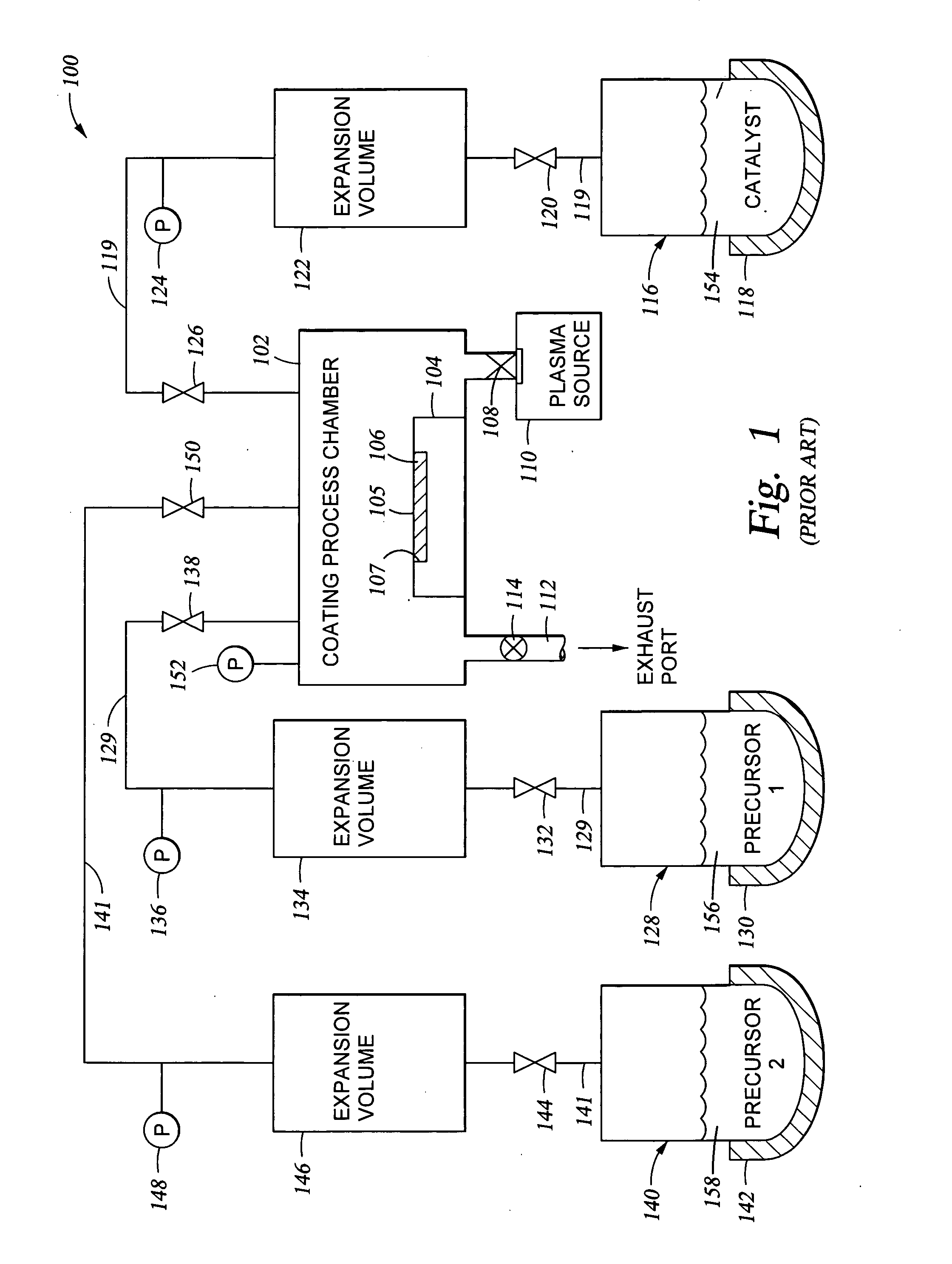
[0026] We have developed an improved vapor-phase deposition method and apparatus for the application of layers and coatings on various substrates. The method and apparatus are useful in the fabrication of biotechnologically functional devices, Bio-MEMS devices, and in the fabrication of microfluidic devices for biological applications. The coating formation method typically employs a batch-like addition and mixing of all of the reactants to be consumed in a given process step, whether that step is one in a series of steps or is the sole step in a coating formation process. In some instances, the coating formation process may include a number of individual steps where repetitive reactive processes are carried out in each individual step. The apparatus used to carry out the method provides for the addition of a precise amount of each of the reactants to be consumed in a single reaction step of the coating formation process. The apparatus may provide for precise addition of quantities of different combinations of reactants during each individual step when there are a series of different individual steps in the coating formation process.
[0033] With reference to chlorosilane-based coating systems of the kind described in the Background Art section of this application, for example, and not by way of limitation, the degree of hydrophobicity of the substrate after deposition of an oxide bonding layer and after deposition of an overlying silane-based polymeric coating can be uniformly controlled over the substrate surface. By controlling a deposited bonding layer (for example) surface coverage and roughness in a uniform manner (as a function of oxide deposition parameters described above, for example and not by way of limitation), we are able to control the concentration of OH reactive species on the substrate surface. This, in turn, controls the density of reaction sites needed for subsequent deposition of a silane-based polymeric coating. Control of the substrate surface active site density enables uniform growth and application of high density self-aligned monolayer coatings (SAMS), for example.
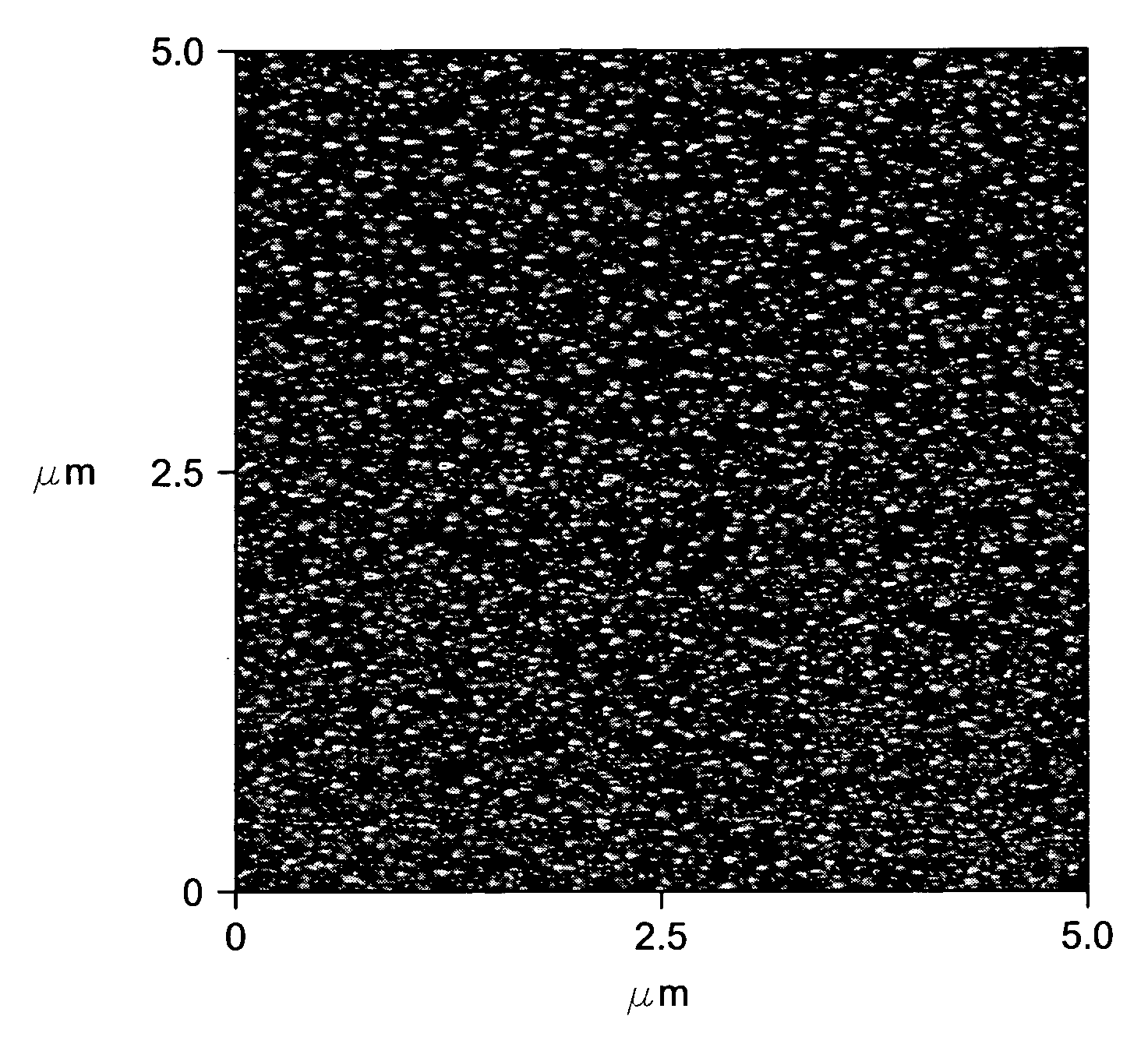
[0035] By controlling the total pressure in the vacuum processing chamber, the number and kind of vaporous components charged to the process chamber, the partial pressure of each vaporous component, the substrate temperature, the temperature of the process chamber walls, and the time over which particular conditions are maintained, the chemical reactivity and properties of the coating can be controlled. By controlling the process parameters, both density of film coverage over the substrate surface and structural composition over the substrate surface are more accurately controlled, enabling the formation of very smooth films, which typically range from about 0.1 nm to less than about 5 nm, and even more typically from about 1 nm to about 3 nm in surface RMS roughness. For oxide films used to provide a hydrophilic surface, the thickness of the oxide film typically ranges from about 20 Å to about 500 Å. When the oxide film is used as a bonding layer, the thickness of the layer may be less. These smooth films can be tailored in thickness, roughness, hydrophobicity / hydrophilicity, and density, which makes them particularly well suited for applications in the field of biotechnology and electronics and as bonding layers for various functional coatings in general.
[0038] Oxide coatings providing hydrophilicity or oxide / polyethylene glycol coatings providing hydrophilicity can be deposited, using the present method, over the topgraphy of various substrates. For example, in one embodiment, such a coating may be applied over the interior surfaces of small wells in a high throughput screening (HTS) micro-plate in order to increase the hydrophilicity of the surface of these wells. Filling these wells with a precise amount of liquid consistently can be very difficult. Often the solvent in which a sample is dissolved (typically water) will bead up and create bubbles, and therefore does not fill the well accurately or completely. If there is a discontinuous volume within the well, the light pattern (autofluorescence) used to measure the sample changes, so that the analytical results become very inaccurate. Another problem arises with air bubbles. For example, in a well having a volume of 12 μl, a 4 μl air bubble can displace enough liquid from the well so that it spills over into other wells on the plate and causes contamination. Finally, inaccurate or incomplete well filling alters the level of liquid within the well, which affects distance impacted measurements. The application of a hydrophilic oxide / PEG coating over the interior surface of a micro-plate well helps alleviate the above problems, to provide more accurate analytical results.
[0042] In summary, disclosed herein is a method of improving the ability of a fluid being charged to a conduit to be drawn into and to flow easily within the conduit, where an interior surface of the conduit is vapor deposition coated with a material having a hydrophilicity or hydrophobicity which is related to the surface tension of the fluid which is to flow within the conduit. The fluid which is to flow within the conduit is typically a hydrophilic fluid (typically, a water-based fluid), and the interior surface of the conduit is coated with a coating which increases its hydrophilicity of the conduit interior surface. Typically, the conduit is an opening in the surface of a substrate, which is typically, for example and not by way of limitation, a plastic selected from the groups consisting of polystyrene, polypropylene, polyethylene, polyvinylchloride, polyimide, polyamide, and acrylic. The invention is particularly applicable when aspect ratio (i.e., the depth of the opening to an equivalent diameter of the opening, or the depth of the conduit divided by a critical width of the conduit) is greater than 1:1, and typically when the aspect ratio ranges from about 1:1 to about 10:1. In some embodiments, the conduit may be a lumen, or a horizontal or vertical channel within a substrate, where the aspect ratio (i.e., the length or depth of the conduit divided by the width of the conduit) is greater than 1:1. The most common vapor-deposited coating used to increase hydrophilicity is an oxide-based coating having a wetting angle ranging from about 5° or less to about 90°.

Problems solved by technology

While this technique enables efficient coating deposition, it frequently results in limited film property control.
In the case of coating a surface of a nanometer scale device, use of liquid phase processing limits device yield due to contamination and capillary forces.
However, the common vapor-phase deposition methods may not permit sufficient control of the molecular level reactions taking place during the deposition of surface bonding layers or during the deposition of functional coatings, when the deposited coating needs to function on a nanometer (nm) scale.
However, too great an RMS surface area is said to result in large surface peaks, widely spaced apart, which begins to diminish the desirable surface area for subsequent reaction with the chloroalkylsilane by vapor deposition.
Too small an RMS surface is said to result in the surface being too smooth, that is to say an insufficient increase in the surface area / or insufficient depth of the surface peaks and valleys on the surface.
However, upon reading these informative descriptions, it becomes readily apparent that control of coating deposition on a molecular level is not addressed in adequate detail in most instances.
Without precise control of the deposition process, the coating may lack thickness uniformity and surface coverage, providing a rough surface.
Any one of these non-uniformities may result in functional discontinuities and defects on the coated substrate surface which are unacceptable for the intended application of the coated substrate.

Method used


Image

  • High aspect ratio performance coatings for biological microfluidics
  • High aspect ratio performance coatings for biological microfluidics
  • High aspect ratio performance coatings for biological microfluidics

Examples


example one

[0094] Deposition of a Silicon Oxide Layer having a Controlled Number of OH Reactive Sites Available on the Oxide Layer Surface

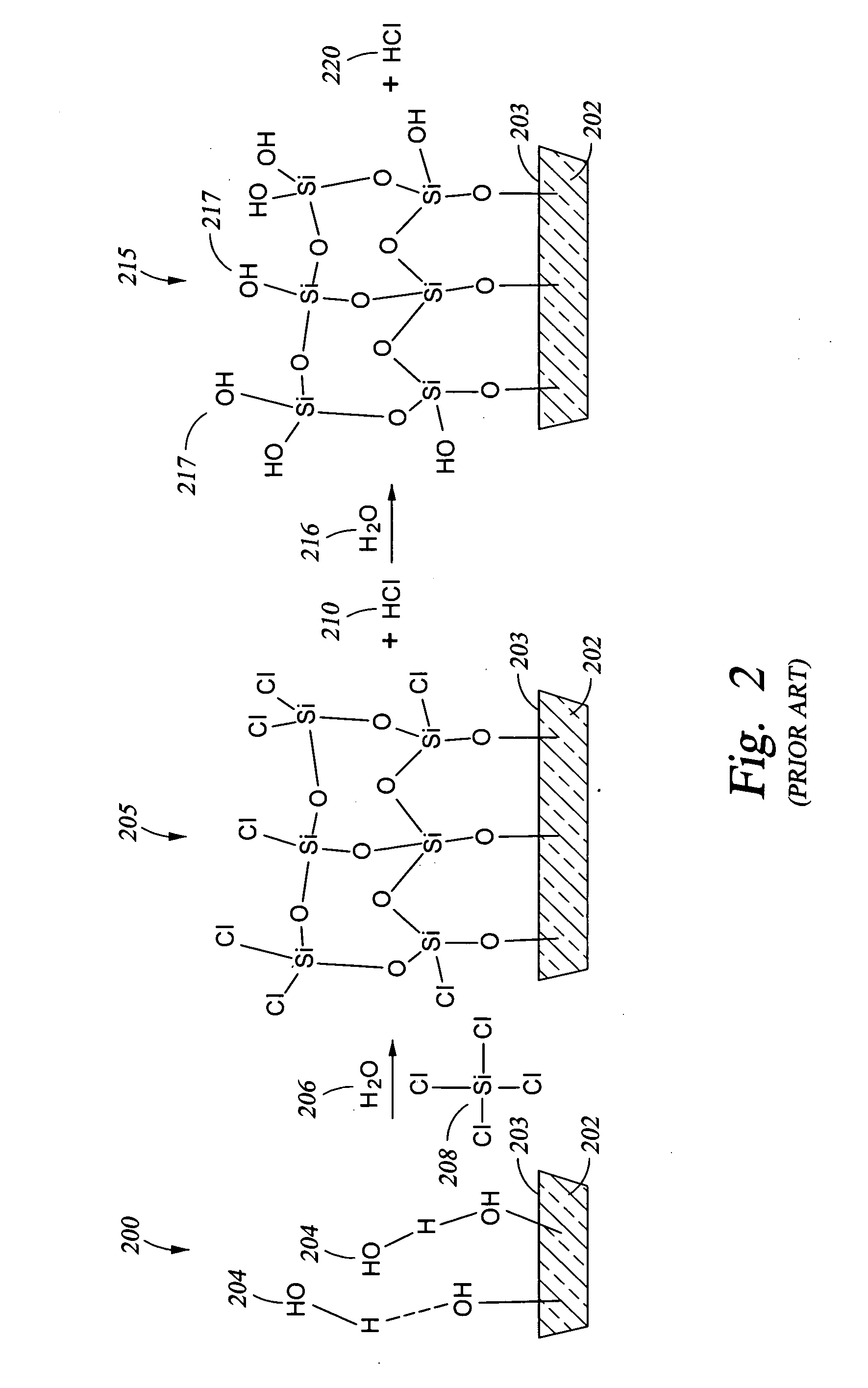
[0095] A technique for adjusting the hydrophobicity / hydrophilicity of a substrate surface (so that the surface is converted from hydrophobic to hydrophilic or so that a hydrophilic surface is made more hydrophilic, for example) may also be viewed as adjusting the number of OH reactive sites available on the surface of the substrate. One such technique is to apply an oxide coating over the substrate surface while providing the desired concentration of OH reactive sites available on the oxide surface. A schematic 200 of the mechanism of oxide formation in shown in FIG. 2. In particular, a substrate 202 has OH groups 204 present on the substrate surface 203. A chlorosilane 208, such as the tetrachlorosilane shown, and water 206 are reacted with the OH groups 204, either simultaneously or in sequence, to produce the oxide layer 205 shown on surface 203 of subst...

example two

[0097] In the preferred embodiment discussed below, the silicon oxide coating was applied over a glass substrate. The glass substrate was treated with an oxygen plasma in the presence of residual moisture which was present in the process chamber (after pump down of the chamber to about 20 mTorr) to provide a clean surface (free from organic contaminants) and to provide the initial OH groups on the glass surface.

[0098] Various process conditions for the subsequent reaction of the OH groups on the glass surface with vaporous tetrachlorosilane and water are provided below in Table I, along with data related to the thickness and roughness of the oxide coating obtained and the contact angle (indicating hydrophobicity / hydrophilicity) obtained under the respective process conditions. A lower contact angle indicates increased hydrophilicity and an increase in the number of available OH groups on the silicon oxide surface.

TABLE IDeposition of a Silicon Oxide Layer of Varying Hydrophilicit...

example three

[0106] When the oxide-forming silane and the organo-silane which includes the functional moiety are deposited simultaneously (co-deposited), the reaction may be so rapid that the sequence of precursor addition to the process chamber becomes critical. For example, in a co-deposition process of SiCl4 / FOTS / H2O, if the FOTS is introduced first, it deposits on the glass substrate surface very rapidly in the form of islands, preventing the deposition of a homogeneous composite film. Examples of this are provided in Table III, below.

[0107] When the oxide-forming silane is applied to the substrate surface first, to form the oxide layer with a controlled density of potential OH reactive sites available on the surface, the subsequent reaction of the oxide surface with a FOTS precursor provides a uniform film without the presence of agglomerated islands of polymeric material, examples of this are provided in Table III below.

TABLE IIIDeposition of a Coating Upon a Silicon Substrate*Using Sil...


PUM

PropertyMeasurementUnit
Lengthaaaaaaaaaa
Lengthaaaaaaaaaa
Angleaaaaaaaaaa

Abstract

We have developed an improved vapor-phase deposition method and apparatus for the application of layers and coatings on various substrates. The method and apparatus are useful in the fabrication of biotechnologically functional devices, Bio-MEMS devices, and in the fabrication of microfluidic devices for biological applications. In one important embodiment, oxide coatings providing hydrophilicity or oxide / polyethylene glycol coatings providing hydrophilicity can be deposited by the present method, over the interior surfaces of small wells in a plastic micro-plate in order to increase the hydrophilicity of these wells. Filling these channels with a precise amount of liquid consistently can be very difficult. This prevents a water-based sample from beading up and creating bubbles, so that well can fill accurately and completely, and alleviates spillage into other wells which causes contamination.

Description

[0001] This application is a continuation-in-part application of U.S. patent application Ser. No. 10 / 862,047, filed Jun. 4, 2004, and entitled “Controlled Deposition of Silicon-Containing Coatings Adhered by an Oxide Layer”. This application is also a continuation-in-part of U.S. patent application Ser. No. 10 / 996,520, filed Nov. 19, 2004, and entitled “Controlled Vapor Deposition of Multilayered Coatings Adhered by an Oxide Layer”. Both of these applications are currently pending and both applications are hereby incorporated by reference in their entireties.BACKGROUND OF THE INVENTION [0002] 1. Field of the Invention [0003] The present invention pertains to high aspect ratio performance coatings for biological microfluidics. The microfluidics may be with respect to fluid flow into openings on the surface of a substrate, with respect to flow of a fluid through an enclosed conduit within a substrate, or with respect to fluid flow within an enclosed conduit in general. [0004] 2. Brief...

Claims


Application Information

Patent Timeline
IPC IPC(8): C23C16/00C23C16/02C23C16/40
CPCB05D1/185B05D1/60B05D5/04B05D7/22B05D7/222B05D2254/04B82Y30/00C23C16/0227C23C16/045C23C16/402Y10T436/11Y10T428/1383Y10T29/49432
Inventor KOBRIN, BORISCHINN, JEFFREY D.NOWAK, ROMUALDYI, RICHARD C.
Owner SPTS TECH LTD
Learn More