
Production of hollow ceramic membranes by electrophoretic deposition

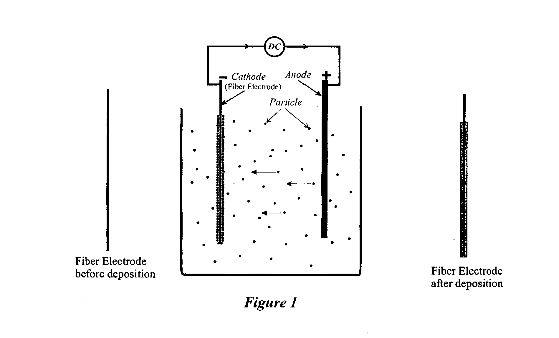
a technology of electrophoretic deposition and ceramic membranes, which is applied in the direction of electrophoresis, electrolysis, fuel cells, etc., can solve the problems of difficult and costly methods, ceramic materials, and unavoidable hydrogen evolution, and achieve the effect of preventing infiltration of particulate materials

Inactive Publication Date: 2003-09-25
INNOTECH ALBERTA INC
View PDF5 Cites 41 Cited by
  • Summary
  • Abstract
  • Description
  • Claims
  • Application Information

AI Technical Summary

Benefits of technology

[0014] The fibre core may be a bundle of individual fibres which is infiltrated by the particulate material upon electrophoretic deposition such that upon removal of the fibre core, the membrane comprises a hollow core comprising a plurality of elongate cylindrical pores. Alternatively, the fibre core may be coated with an organic binder to prevent infiltration of the particulate material during electrophoretic deposition.
[0015] In one embodiment, the porosity of the membrane may be controlled by controlling the duration and temperature of the sintering step, by controlling the particle size, size distribution and / or the surface area of the ceramic material, by adding sintering additives in the suspension where the additives will deposit concurrently with the ceramic material, by adding a combustible particulate material, such as carbon, carbon black or a suitable organic or polymeric material, to the ceramic material which is concurrently deposited with the ceramic material, wherein said combustible material is removed by combustion during the sintering step.
[0066] Porosity of the ceramic tubes or hollow fibres or hollow ceramic membranes may be enhanced by mixing combustible particles such as carbon black, carbon, graphite, different polymer powders and cellulose base powders into the ceramic particle suspension such that the combustible particles co-deposit during EPD. Then, when the ceramic coated core is heated to sinter the hollow ceramic membranes and remove the core, the combustible particles will also be burned off, resulting in a more porous ceramic membrane.
[0072] To produce a tubular SOFC in one embodiment, an inner electrode layer, which may be either an anode or a cathode, is deposited onto the fibre core to a desired thickness. Secondly, a thin solid electrolyte layer is then deposited. This intermediate product is then sintered to achieve full density of the solid electrolyte layer while maintaining the porosity on the inner electrode. By using different average particle sizes for the solid electrolyte and anode deposition suspensions, the anode layer and the electrolyte layer will have two different sintering kinetics so that for a given sintering cycle, the electrolyte would be nonporous (fully dense) but the anode would be porous. The porosity of the anode layer may be enhanced using combustible particles into the anode particle suspension. In addition or alternatively, sintering additives may be added to the electrolyte layer to enhance the densification of the electrolyte layer. Lastly, the cathode layer is deposited onto the electrolyte layer by any suitable means including dip-coating, brushing, spraying or sol-gel coating, followed by a final sintering stage of the tubular SOFC membrane to partially densify the outer cathode layer and bond the outer cathode layer to the electrolyte layer.

Problems solved by technology

Because the sol is aqueous, hydrogen evolution is unavoidable and steps must be taken to minimize hydrogen evolution and to permit hydrogen to escape such that it does not embed in the deposited material.
As a result, the resulting ceramic materials, after sintering, are not porous.
These are difficult and costly methods.

Method used


Image

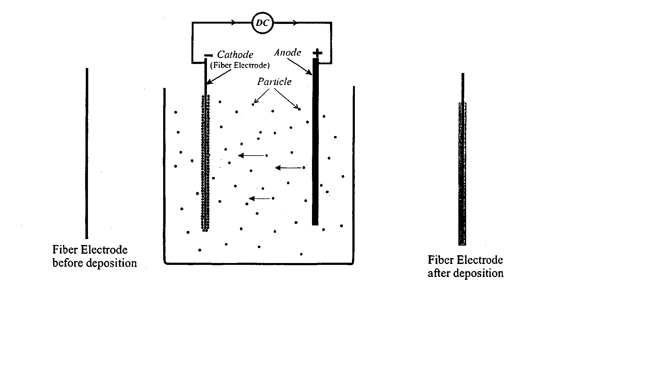
  • Production of hollow ceramic membranes by electrophoretic deposition
  • Production of hollow ceramic membranes by electrophoretic deposition
  • Production of hollow ceramic membranes by electrophoretic deposition

Examples


example 2

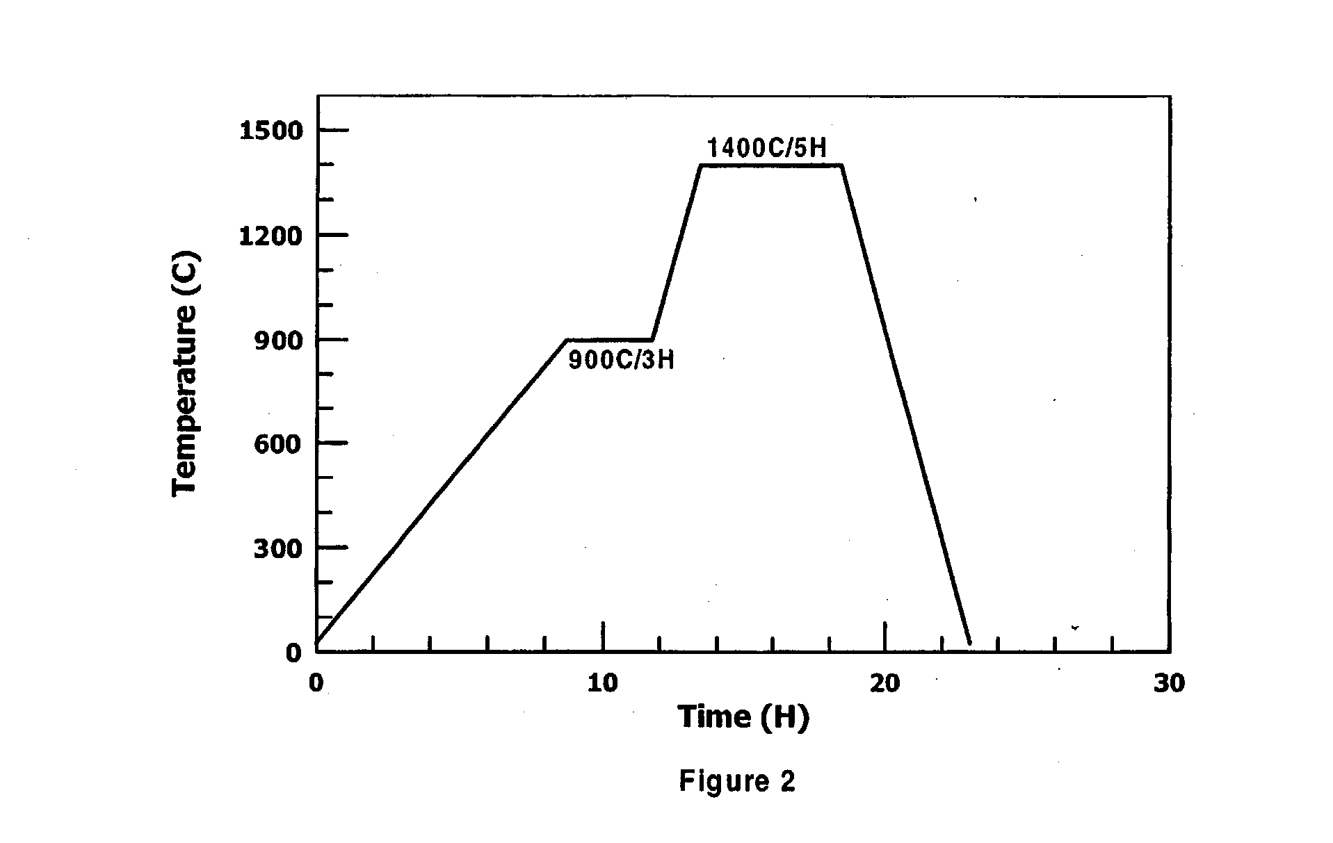
[0080] In one example, particulate carbon black having a particle size range of about 20 nm to about 150 nm, was added to the alumina suspension prepared in accordance with Example 1 above in about 29 v / o such that the carbon and alumina were co-deposited onto the fibre core. The resulting ceramic membrane was sintered at 1250.degree. C. for 5 hours. FIG. 4 shows that the carbon black increases the porosity of the membrane.

example 3

[0081] An untreated fibre tow was used to deposit alumina particles as otherwise described in Example 1 above. The resulting ceramic membrane having a porous core is shown in FIGS. 5A and 5B. The core has a plurality of longitudinal holes, which correspond to individual filaments of the fibre tow.

example 4

[0082] Fibre cores comprising fibre tow of varying sizes was used for depositing alumina particles as otherwise described in Example 1 above. The fibre tow diameters used were approximately 400 .mu.m (FIG. 7) to 650 .mu.m (FIG. 8). The resulting ceramic tubes are shown in FIGS. 7 and 8.


PUM

PropertyMeasurementUnit
Lengthaaaaaaaaaa
Areaaaaaaaaaaa

Abstract

The present invention provides methods for producing hollow ceramic membranes by electrophoretic deposition. The hollow ceramic membranes may have a small cross-sectional area of about 1.0x10<-5 >mm<2 >to about 25 mm<2>. The cross-sectional configuration of the hollow ceramic membranes may be any geometry such as circular, square, rectangular, triangular or polygonal. The hollow ceramic membranes produced by the methods of the present invention may have multiple layers but always the innermost layer, or the first deposited layer is porous and made by electrophoretic deposition. Subsequent layers may be porous or non porous and deposited before or after sintering the first layer. If it is deposited after sintering, it may require additional sintering steps. Additional layers may be deposited by further electrophoretic deposition, sol-gel coating, dip coating, vacuum casting, brushing, spraying or other known techniques.

Description

[0001] This application is a divisional application of U.S. patent application Ser. No. 09 / 583,274 filed on May 31, 2000 which claimed the priority benefit of Canadian Application No. 2,308,092 filed on May 10, 2000.BACKGROUND OF INVENTION[0002] The present invention relates to the production of hollow ceramic membranes by electrophoretic deposition. In particular, the present invention relates to the production of small cross-sectional area hollow ceramic membranes by electrophoretic deposition.[0003] It is well known to deposit coatings of material by electrophoretic deposition ("EPD"). EPD is a combination of electrophoresis and deposition. Electrophoresis is the movement of charged particles in an electric field. Deposition is the coagulation of particles into a mass.[0004] In U.S. Pat. No. 5,580,835 to Dalzell et al., a process for creating ceramic fibers by EPD is described. The ceramic fibers produced by this process are fully dense, non-porous fibers. The described EPD proce...

Claims


Application Information

Patent Timeline
IPC IPC(8): C04B38/00C04B38/06C25D13/02C25D13/14C25D15/00H01B13/00H01M4/88H01M8/124
CPCC04B38/00C04B38/065C04B41/009C04B41/5031C04B2111/00413C04B2111/00801C04B2111/00853Y02E60/525C25D13/02C25D13/14H01M8/1206Y02E60/521C04B35/00C04B38/0003C04B38/007C04B38/06C04B38/069C04B41/4564C04B14/303C04B30/02H01M8/1231Y02E60/50Y02P70/50
Inventor SARKAR, PARTHA
Owner INNOTECH ALBERTA INC
Learn More