
High polymer electrolyte fuel cell

a fuel cell, high-polymer technology, applied in cell components, active material electrodes, electrochemical generators, etc., can solve the problems of hydrophilic porous electrodes clogged with water, likely to interfere with gas permeation, etc., to achieve the effect of sacrificing gas permeability and water repellency

Inactive Publication Date: 2002-12-19
PANASONIC CORP
View PDF8 Cites 23 Cited by
  • Summary
  • Abstract
  • Description
  • Claims
  • Application Information

AI Technical Summary

Benefits of technology

[0046] Typical examples of conductive carbon fibers include PAN-based, pitch-based, rayon-based (cellulose-based), and phenol-based (kynol-based) graphite fibers, and the graphitization degree that they can reach differs depending on the properties of their starting materials. For example, in the case of PAN-based and mesophase pitch-based (also called liquid crystal pitch or anisotropic pitch) graphite fibers, long fibers having a high degree of orientation are obtained in the spinning stage, and the starting materials have simple structure and can readily form a benzene ring. Therefore, if such a fiber is carbonized and graphitized, a carbon fiber with a high degree of crystal orientation and a high degree of graphitization is obtained. On the other hand, in the case of rayon-based and phenol-based graphite fibers, the degree of crystal orientation and the degree of graphitization are both low because of the difficulty in forming a benzene ring due to the complexity of the starting materials and a low degree of crystal orientation originated in the materials.
[0073] By suitably combining the above-mentioned techniques, it is possible to impart a desired hydrophilicity to the hydrophilic part while ensuring sufficient gas permeability in the water repellent part.

Problems solved by technology

However, if the entire surface is covered with the hydrophilic porous electrode, there will be a problem that a phenomenon (flooding) in which the hydrophilic porous electrode is clogged with water and interferes with gas permeation is likely to occur.

Method used


Image

  • High polymer electrolyte fuel cell
  • High polymer electrolyte fuel cell
  • High polymer electrolyte fuel cell

Examples


example 2

[0099] A mesophase pitch-based carbon fiber raw yarn (which was spun but had not been stabilized) was woven into a fabric with a thickness of 150 .mu.m, and a phenol-based carbon fiber raw yarn was sewn in the fabric to have a thickness of 600 .mu.m. The resulting fabric was graphitized after the stabilization and carbonization processes so as to produce an electrode as shown in FIG. 6. Thereafter, the fabric was activated by steam oxidation in a continuous furnace under the condition of 800.degree. C. and 240 seconds. The specific surface area and the hydrophilicity of a part that forms the bottom of the gas flow path and the side-wall part were evaluated before and after the activation, and the results of evaluation are shown in Table 2. As shown in Table 2, a significant increase was observed as a result of the activation, particularly, in the specific surface area and the hydrophilicity of the flow path's side-wall part made from the phenol-based fiber.

2 TABLE 2 Specific surface...

example 3

[0101] A PAN-based carbon fiber which had gone through up to the carbonization process was cut to a fiber length of 2 mm, and then the fiber was made into paper to form a sheet having a thickness of 50 .mu.m and 0.12 g / cm.sup.2 as the weight per unit area.

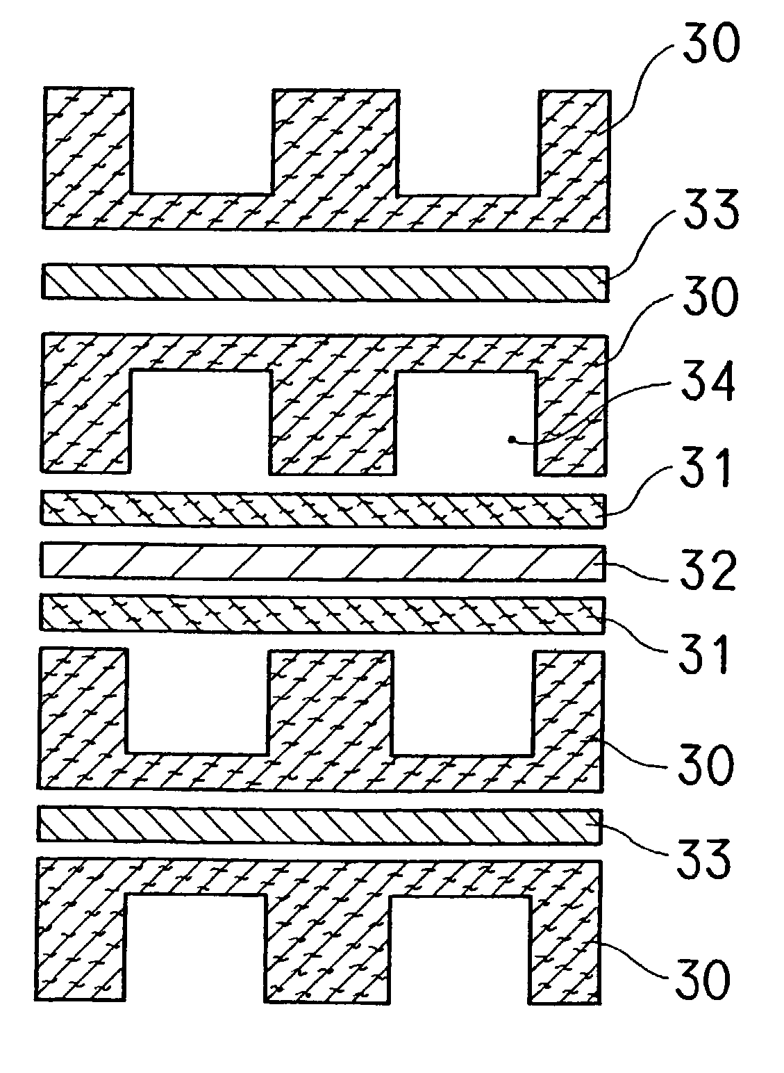
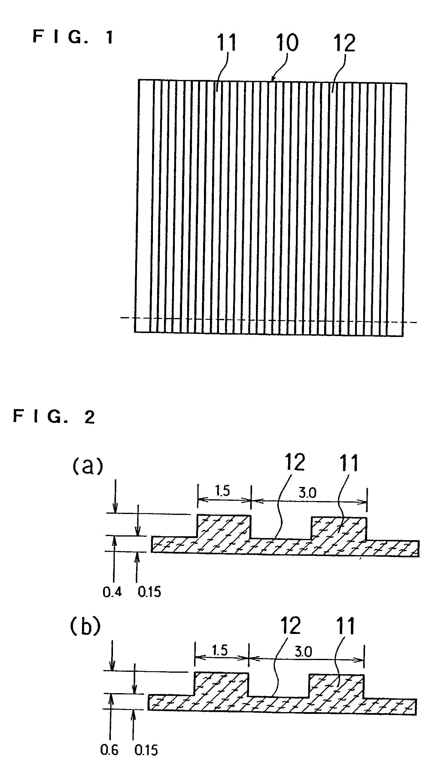
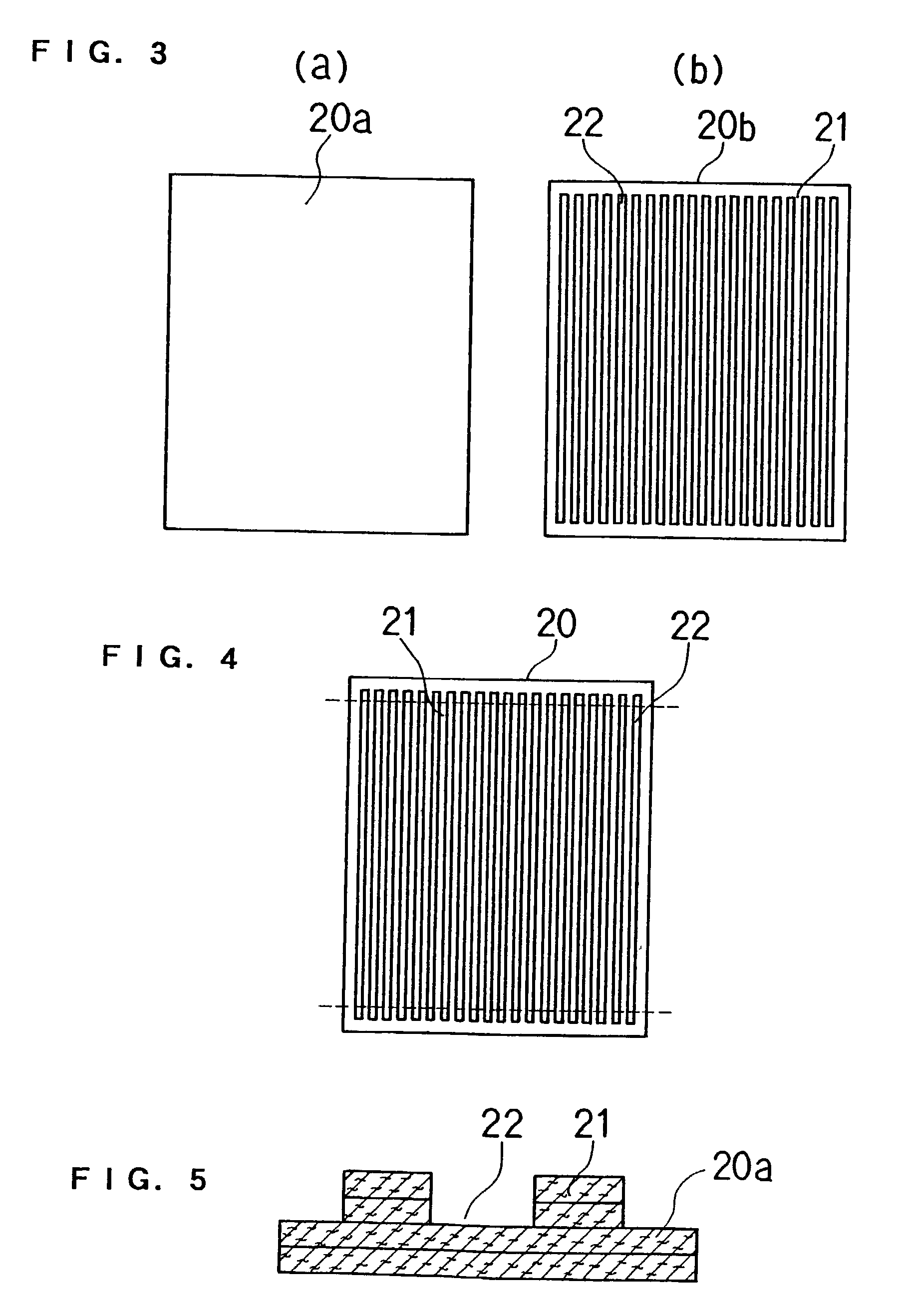
[0102] Thereafter, as shown in FIG. 3 and FIG. 4, three sheets which were not stamped and eight stamped sheets were joined together using an aqueous solution of carboxylmethyl cellulose as a binder while positioning them. The resulting sheet was graphitized at 2400.degree. C. to produce a single electrode. The stamped shape of sheet B had a groove width of 1.5 mm and a pitch of 3 mm.

[0103] For this single electrode, a hydrophilic treatment was applied to the side-wall part by using a technique shown in FIG. 11. Specifically, an ink was prepared by adding 25 parts by weight of acetylene black (manufactured by Denki Kagaku Kogyo K.K.), 15 parts by weight of silica gel (particle size: 10 to 30 .mu.m, JIS A grade) and 5 parts by weight...

example 4

[0104] After binding the following raw carbonized papers with a pitch-based binder, the resulting paper was graphitized at 2450.degree. C. under an inert gas atmosphere for three hours to fabricate an electrode sheet X1 composed of four layers.

[0105] First layer: mesophase pitch-based carbonized paper (fiber diameter of 12 .mu.m, fiber length of 5 mm, and a thickness of 150 .mu.m).

[0106] Second layer: highly elastic PAN-based carbonized paper (fiber diameter of 6.5 .mu.m, fiber length of 5 mm, and a thickness of 150 .mu.m).

[0107] Third layer: anisotropic pitch-based carbonized paper (fiber diameter of 13 .mu.m, fiber length of 2 mm, and a thickness of 80 .mu.m).

[0108] Fourth layer: phenol-based carbonized paper (fiber diameter of 11 .mu.m, fiber length of 2 mm, and a thickness of 80 .mu.m).

[0109] After adhering the above-mentioned sheet 80 to a glass for fixture, the sheet 80 was polished to expose the respective polished surfaces of the first layer 80a, second layer 80b, third laye...


PUM


Abstract

The present invention discloses an improved gas diffusion layer for use in porous electrodes of polymer electrolyte fuel cells. The gas diffusion layer comprises a gas flow path having a bottom face facing an electrolyte membrane, and the properties of a carbon fiber that forms the bottom face of the gas flow path are different from the properties of a carbon fiber that forms the side wall of the gas flow path and / or the top face of the gas flow path. It is preferable that there is a difference in the graphitization degree, graphite orientation degree or fiber microstructure, and the hydrophilic group density of the carbon fiber forming the bottom face of the gas flow path is particularly small. Accordingly, it is possible to obtain a gas diffusion layer imparted with water retention property, without sacrificing the gas permeability.

Description

[0001] The present invention relates to polymer electrolyte fuel cells, and more particularly relates to an improvement of the porous electrodes in the polymer electrolyte fuel cells.[0002] The basic principle of the polymer electrolyte fuel cell includes exposing one side of a hydrogen ion conductive polymer electrolyte membrane to a fuel gas such as hydrogen and exposing the other side to oxygen to synthesize water by chemical reaction through the electrolyte membrane, and extracting the resulting reaction energy electrically. The structure of this type of fuel cell is shown in FIG. 23.[0003] A hydrogen ion conductive polymer electrolyte membrane 1 and a pair of porous electrodes 2 including a catalyst, which sandwich this electrolyte membrane 1, are joined integrally by heat press or other method. The resulting unit is called an electrolyte membrane-electrode assembly (MEA), and can be handled independently. Disposed outside of the electrodes 2 are a pair of conductive separator ...

Claims


Application Information

Patent Timeline
IPC IPC(8): H01M4/86H01M4/88H01M4/94H01M4/96H01M8/10
CPCH01M4/8605H01M4/96H01M8/0234Y02E60/522H01M8/04126H01M8/1004H01M8/0245Y02E60/50
Inventor KOBAYASHI, SUSUSMUHOSAKA, MASATO
Owner PANASONIC CORP
Learn More