
Modification method for SnO2 electron selective transmission layer

A selective transmission and modification technology, applied in the field of solar cells, can solve the problems of not being suitable for flexibility requirements, increasing parasitic absorption loss, reducing transmittance, etc., to improve mobility and electron extraction ability, improve crystal quality and Stability and the effect of reducing energy level mismatch

Active Publication Date: 2019-11-26
ZHEJIANG ZHENENG TECHN RES INST +1
View PDF24 Cites 4 Cited by
  • Summary
  • Abstract
  • Description
  • Claims
  • Application Information

AI Technical Summary

Problems solved by technology

[0014] 1. Doping with metal elements often reduces transmittance and increases parasitic absorption loss;
[0015] 2. The doping of metal elements often causes the work function to increase, which aggravates the energy level mismatch of the battery;
[0016] 3. Many doping elements are rare metals, which are expensive and not conducive to industrialization;
[0017] 4. Surface plasma treatment is only effective on the surface;
[0018] 5. When high-temperature annealing consumes energy, it is not suitable for flexibility requirements, and the effect may not be very good;
[0019] 6. Low temperature annealing of SnO 2 The crystallinity is low, and the defect state is serious;
[0020] 7. The interface modification layer polyfullerene and its derivatives are expensive, poor in stability, and only have a modification effect on the interface, while ignoring SnO 2 inside the film;
[0021] 8. Methods such as physical vapor deposition and chemical vapor deposition are expensive and often have large roughness;
[0022] 9. Chemical bath, electrochemical deposition, sol-gel method, etc. often have large roughness and uneven surface morphology;
[0023] 10. The atomic layer deposition method has slow speed and small area, which is not suitable for industrial production

Method used


Image

  • Modification method for SnO2 electron selective transmission layer
  • Modification method for SnO2 electron selective transmission layer
  • Modification method for SnO2 electron selective transmission layer

Examples


Embodiment 1

[0043] in SnO 2 Add 7.4at% phosphoric acid (Sinopharm) to the sol (Alfa Aesar), 5000rpm, 30s homogeneous spin coating, dry at 100°C for 10min, anneal at 180°C for 30min in nitrogen. Thereafter spin-coated perovskite layer ((FAPbI 3 ) 0.85 (MAPbBr 3 ) 0.15 ), a hole transport layer (Spiro-OMeTAD), and a silver electrode with a thickness of 80 nm.

[0044] Fourier transform infrared spectroscopy analysis shows that phosphorus exists in the form of polyphosphate, such as figure 1 shown.

[0045] Testing monolayer SnO with a semiconductor parameter meter 2 The J-V curve of the film, the carrier mobility is calculated according to the Mott-Gurney law. It was found that after doping SnO with phosphoric acid 2 The electron mobility is changed from 1.70×10 -4 cm 2 V -1 the s -1 Increased to 5.08×10 -4 cm 2 V -1 the s -1 .

[0046] The main performance parameters of solar cells before and after doping are shown in the table below, which shows that the performance of th...

Embodiment 2

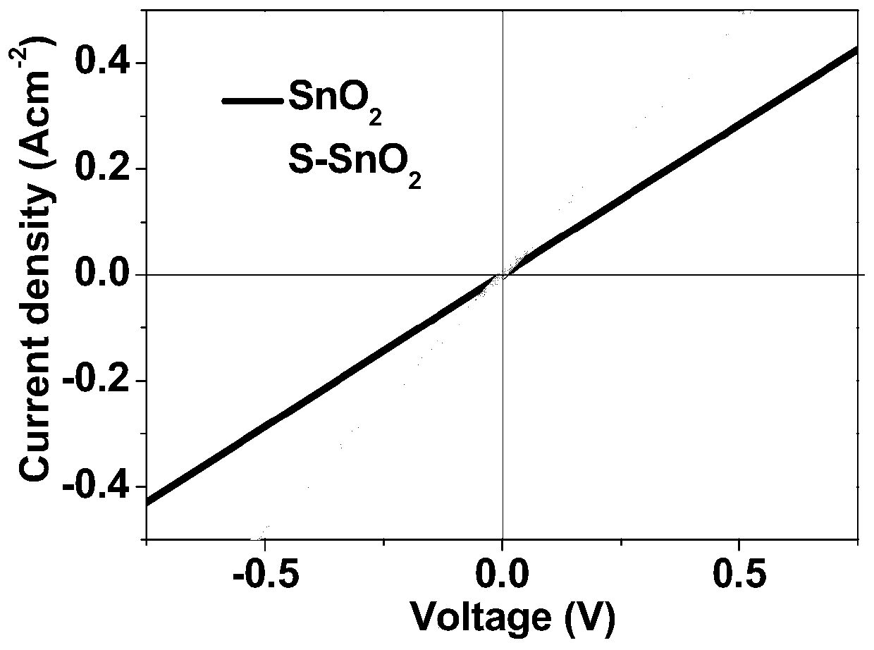
[0050] in SnO 2 Add 2at% ammonium sulfide (Sinopharm) to the sol (Alfa Aesar), 5000rpm, 30s spin coating, drying at 100°C for 10min, annealing at 180°C for 30min in nitrogen. Thereafter spin-coated perovskite layer ((FAPbI 3 ) 0.85 (MAPbBr 3 ) 0.15 ), a hole transport layer (Spiro-OMeTAD), and a silver electrode with a thickness of 80 nm.

[0051] Fourier transform infrared spectroscopy analysis showed that sulfur element combined with Sn atoms in the form of S-Sn, passivating SnO 2 surface, such as figure 2 shown.

[0052] J-V curve analysis shows that the SnO after ammonium sulfide doping 2 The conductivity is greatly improved, such as image 3 shown.

[0053] The efficiency statistics of perovskite solar cells before and after doping are as follows: Figure 4 As shown, it can be clearly seen that the battery efficiency is greatly improved after doping with ammonium sulfide.

Embodiment 3

[0055] in SnO 2 Add 2at% taurine (Sinopharm) to the sol (Alfa Aesar), 5000rpm, 30s homogeneous spin coating, dry at 100°C for 10min, anneal at 180°C for 30min in nitrogen. Thereafter spin-coated perovskite layer ((FAPbI 3 ) 0.85 (MAPbBr 3 ) 0.15 ), a hole transport layer (Spiro-OMeTAD), and a silver electrode with a thickness of 80 nm.

[0056] The J-V curves of solar cells before and after doping are as follows: Figure 5 As shown, it can be seen that the short-circuit current density of the battery is significantly improved after doping with taurine.


PUM

PropertyMeasurementUnit
Electron mobilityaaaaaaaaaa

Abstract

The invention relates to a modification method for a SnO2 electron selective transmission layer. The modification method comprises steps of (1) doping agent that is inorganic acid, sulfonic acid, amino acid or sulfur-containing ammonium salt, and doping concentration of 0.1-10at%; (2) preparation of a precursor solution: adding a required doping agent to prepared SnO2 sol with concentration of 1-5wt% according to the doping concentration, ultrasonic oscillating for 30-60 minutes at 30-80W to fully mix and uniformly disperse the doping agent; (3) preparation of a film: cleaning ITO glass, thentreating the ITO glass with UV ozone, and then spin-coating the prepared doping SnO2 sol on the surface of the ITO glass; and (4) film annealing. The modification method for the SnO2 electron selective transmission layer has the beneficial effects of improving SnO2 carrier migration rate and electronic extraction capability, lowering energy level mismatch of SnO2 and a perovskite layer, improvingoptical transmittance of a SnO2 film, improving crystalizing quality and stability of the perovskite layer, and improving short circuit current density, open-circuit voltage, fill factor and efficiency of a perovskite battery.

Description

technical field [0001] The present invention relates to a kind of SnO 2 The invention relates to a method for modifying an electron selective transport layer, which belongs to the technical field of solar cells. Background technique [0002] SnO 2 As a common n-type oxide semiconductor material, it is often used as an electron transport layer material for perovskite solar cells. However, in practical applications, there are generally problems such as serious energy level mismatch, low actual carrier concentration, and large surface defect states. To solve these problems, the current popular methods are as follows: [0003] 1. Metal element doping [0004] Doping is a common method to adjust the electrical properties of materials, so it is also commonly used to adjust the electrical properties of SnO 2 The electrical properties of the electron transport layer, in order to obtain higher application value. The ion radius of Li element is small, and the work function of it...

Claims


Application Information

Patent Timeline
IPC IPC(8): H01L51/42H01L51/46H01L21/02
CPCH01L21/02565H01L21/02584H01L21/02628H01L21/02667H01L21/02694H10K30/15H10K2102/101Y02E10/549
Inventor 寿春晖姜二帅盛江艾余前叶继春闫宝杰闫锦邬荣敏丁莞尔
Owner ZHEJIANG ZHENENG TECHN RES INST
Learn More