Copper foil for wiring board
A wiring substrate, copper foil technology, applied in conductive materials, metal/alloy conductors, conductive materials, etc., can solve the problems of insufficient softening and high flexibility, and achieve high bending and flexibility. Effect
- Summary
- Abstract
- Description
- Claims
- Application Information
AI Technical Summary
Problems solved by technology
Method used
Image
Examples
Embodiment
[0084] Hereinafter, the present invention will be described in further detail based on examples, but the present invention is not limited to these.
[0085] Example
[0086] (Production of copper foil)
[0087] Examples 1 to 8 use #2000 abrasive paper to polish the surface, use a cathode made of polished titanium, and use the electrolyte described below at a bath temperature of 30 to 75°C and a current density of 30 to 100 A / dm 2 Electricity was applied to the thickness shown in Table 1 to produce electrolytic copper foil.
[0088] (Electrolyte composition)
[0089] With copper sulfate 200-500g / L and sulfuric acid 20-200g / L as the basic plating solution composition, the electrolyte solution was prepared by adding the additives described in Table 1 to the basic plating solution. In addition, the organic additive A uses the structure of Chemical Formula 2, the additive represented by 2-mercapto-5-benzimidazole sulfonic acid, and the structure of Chemical Formula 3, which is represented b...
Embodiment 9
[0095] Example 9 is a rolled copper alloy foil manufactured by casting and rolling methods. The raw materials of copper, chromium (Cr), tin (Sn), and zinc (Zn) are melted in a high-frequency furnace, and then cast at a cooling rate of 0.5 to 150°C / sec to obtain an ingot. The ingot contains an alloy composition of 0.3 mass% (mass%) of Cr (chromium), 0.3 mass% of Sn (tin), and 0.1 mass% of zinc, and the remainder is a substance formed by copper and inevitable impurities.
[0096] Then, the obtained ingot was subjected to a homogenization heat treatment at a temperature of 1000°C for 8 hours, and then directly hot rolled at 600 to 1050°C. Here, the temperature range of 600 to 1050°C for hot rolling is the temperature range from the start to the end of hot rolling. The processing rate is 85-97%.
[0097] Furthermore, at least between 600°C and 200°C at a cooling rate of 30°C / sec, cooling by water cooling, performing intermediate cold rolling with a work rate of 80-99.8%, and performi...
Embodiment 2
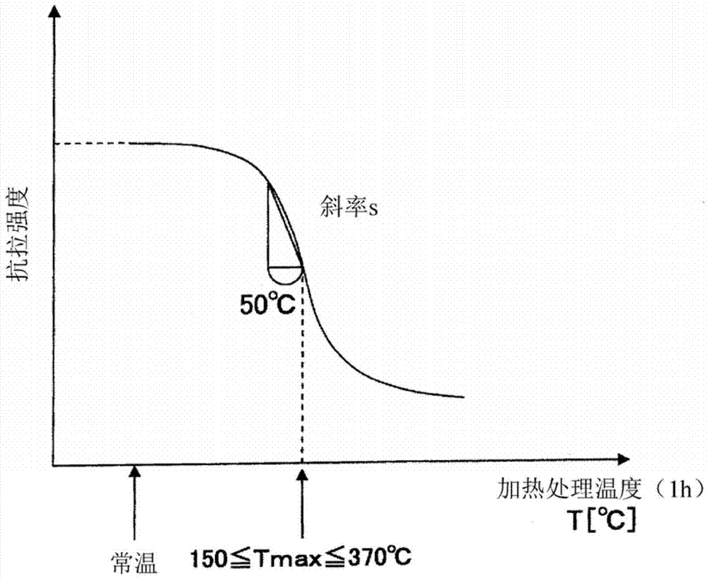
[0128] The ratio of Tmax to normal tensile strength of Example 2 exceeds 70%, and the transportability and flexibility when heated at 300°C are slightly worse, but the performance can still withstand practical use.
[0129] Compared with Example 9 using rolled copper foil, Example 4 using electrolytic copper foil showed excellent results in both the handling test and the number of bending.
PUM
| Property | Measurement | Unit |
|---|---|---|
| thickness | aaaaa | aaaaa |
| tensile strength | aaaaa | aaaaa |
| tensile strength | aaaaa | aaaaa |
Abstract
Description
Claims
Application Information
 - R&D
- Intellectual Property
- Life Sciences
- Materials
- Tech Scout
- Unparalleled Data Quality
- Higher Quality Content
- 60% Fewer Hallucinations
Browse by: Latest US Patents, China's latest patents, Technical Efficacy Thesaurus, Application Domain, Technology Topic, Popular Technical Reports.
© 2025 PatSnap. All rights reserved.Legal|Privacy policy|Modern Slavery Act Transparency Statement|Sitemap|About US| Contact US: help@patsnap.com


