
Film solar energy battery and manufacturing method thereof

A solar cell and thin film technology, applied in the field of solar cells, can solve problems such as unsatisfactory welding performance, poor welding performance, and film layer shedding, and achieve the effects of overcoming looseness and oxidation, reducing production costs, and increasing welding performance

Inactive Publication Date: 2014-07-23
SHEN ZHEN TRONY SCI & TECH DEV CO LTD
View PDF7 Cites 0 Cited by
  • Summary
  • Abstract
  • Description
  • Claims
  • Application Information

AI Technical Summary

Problems solved by technology

At present, the film structure design of the back electrode has changed from a simple single-layer structure to a multi-layer structure. For example, the back electrode structure of the Chinese patent ZL200910209157.4 "A Solar Cell and Manufacturing Method" is AZO layer+transition layer+Ag layer+ The metal protective layer, the transition layer is located between the AZO layer and the Ag layer, which can improve the adhesion between the AZO layer and the Ag layer and ensure the service life of the battery. However, Comparative Document 1 uses a single layer of silver as the reflective layer, which is costly, and the silver film The metal protective layer on the surface has no function of increasing welding, which cannot meet the customer's requirements for welding performance
And the back electrode structure of the patent ZL201010523713.8 "Thin Film Solar Cell Back Electrode" is Y:ZnO+Ag+Y:ZnO+Ag+metal film layer, which can improve the conductivity and reflectivity of the back electrode, but Y:ZnO layer and Ag The adhesion between the layers is poor, which is easy to cause the film layer to fall off, and the metal film layer is made of Ti / Ni / Al, which has poor welding performance

Method used


Image

  • Film solar energy battery and manufacturing method thereof
  • Film solar energy battery and manufacturing method thereof
  • Film solar energy battery and manufacturing method thereof

Examples


Embodiment 1

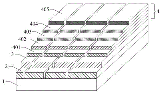
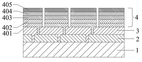
[0021] A thin-film solar cell includes a base substrate, a front electrode layer, a photoelectric conversion layer, and a back electrode layer. A reflective layer, a second reflective layer and a solder-enhancing protective layer, wherein the transparent conductive layer is aluminum-doped zinc oxide (AZO) with a thickness of 50-300nm, because AZO is relatively cheap, non-toxic and environmentally friendly;

[0022] The transition layer is chromium (Cr), with a thickness of 5-50nm, because the atomic radius of Cr is between AZO and Ag, which increases the adhesion of AZO and Ag;

[0023] The first reflective layer is silver (Ag), with a thickness of 50-150nm, because Ag has high reflective and conductive properties;

[0024] The second reflective layer is aluminum (Al) with a thickness of 50-300nm, because Al is highly reflective and cheap;

[0025] The welding protection layer is nickel-copper (NiCu) or nickel-vanadium alloy, with a thickness of 40-200nm, and has good welding...

Embodiment 2

[0027] A method for preparing a thin-film solar cell mainly includes: sequentially depositing a front electrode layer, a photoelectric conversion layer, and a back electrode layer on a base substrate, and sequentially depositing a transparent conductive layer, a transition layer, a first reflection layer, and a second electrode layer on the back electrode layer. The second reflective layer and the solder-increasing protective layer are heated before depositing the transparent conductive layer, and the heating temperature is 100-200° C.; and cooled at room temperature after depositing the solder-increasing protective layer.

[0028] The deposition method of each film layer of the back electrode layer is the DC magnetron sputtering vacuum coating method, that is, the deposition of the target is controlled by a DC power supply on a horizontal coating continuous production line, the working gas is argon, and the background pressure is 2 ~6×10 -6 Torr, the working pressure is 1×10 ...

Embodiment 3

[0037] A kind of manufacturing equipment of the back electrode of thin-film solar cell, it is horizontal PVD continuous vacuum coating equipment, comprises heating room, coating room I, coating room II, coating room III, coating room IV, cooling room, coating room I is deposition transparent For the conductive layer, the coating chamber II is for depositing the transition layer, the coating chamber III is for depositing the first reflective layer and the second reflective layer, and the coating chamber IV is for depositing the solder-increasing protective layer.

[0038] Due to the complex structure and high price of the rotating target, but the high utilization rate of the target material; the simplicity of the planar target and the low price, but the low utilization rate of the target material, therefore, considering the cost performance of the target material and the rotating target, the following technical solutions are adopted:

[0039] Among them, the target material of the...


PUM


Abstract

The invention belongs to the technical field of a solar energy battery, and relates to a film solar energy battery and a manufacturing method thereof, for solving the technical problems of welding performance of the back electrode of a film solar energy battery, adhesive force among each film layer and the like. The film solar energy battery is composed of multiple internally series-connected photoelectric units, comprises a front electrode, a photoelectric conversion layer and a back electrode which are sequentially stacked on a substrate, and is characterized in that the back electrode is of a multi-layer structure composed of a transparent conductive layer, a transition layer, a first reflection layer, a second reflection layer and a welding enhancement protective layer. The reflection layer of the back electrode is composed of two membranes, i.e., a silver membrane and an aluminum membrane, and the thickness of the silver membrane is smaller than the thickness of the aluminum membrane, so that the production cost can be effectively reduced; and the aluminum membrane is provided with a nickel copper film layer or a nickel-vanadium alloy film layer so that the back electrode can be protected, and the welding performance of the back electrode can also be improved.

Description

technical field [0001] The invention relates to a thin-film solar cell and a manufacturing method thereof, belonging to the technical field of solar cells. Background technique [0002] Thin-film solar cells are mainly composed of a front electrode layer, a photoelectric conversion layer and a back electrode layer. The properties of these three layers directly affect the conversion efficiency of solar cells. In order to ensure high light transmittance and good conductivity, the front electrode layer generally adopts a single layer of tin dioxide or indium tin oxide. The back electrode layer must have good electrical and optical properties. At present, the film structure design of the back electrode has changed from a simple single-layer structure to a multi-layer structure. For example, the back electrode structure of the Chinese patent ZL200910209157.4 "A Solar Cell and Manufacturing Method" is AZO layer+transition layer+Ag layer+ The metal protective layer, the transitio...

Claims


Application Information

Patent Timeline
Patent Type & Authority Applications(China)
IPC IPC(8): H01L31/0224H01L31/046H01L31/056H01L31/18
CPCH01L31/022425H01L31/1876Y02E10/52Y02P70/50
Inventor 李毅盛国浩宋光耀龙鹏王广文
Owner SHEN ZHEN TRONY SCI & TECH DEV CO LTD
Learn More