
Fire retardant coating for steel structure surface of nuclear power plant

A technology for fire-resistant coatings and steel structures, applied in the direction of fire-resistant coatings, polyester coatings, epoxy resin coatings, etc., can solve the problems of affecting the fire-proof effect, chemical corrosion resistance, poor water resistance and solvent resistance, coating loss, etc., to achieve excellent Expansion effect, high mechanical strength, and the effect of increasing the viscosity of the system

Inactive Publication Date: 2014-04-09
CHINA NAT OFFSHORE OIL CORP +3
View PDF4 Cites 23 Cited by
  • Summary
  • Abstract
  • Description
  • Claims
  • Application Information

AI Technical Summary

Problems solved by technology

However, most intumescent fireproof coatings use acrylic resin or water-based resin as the film-forming material, which has poor chemical corrosion resistance, water resistance, and solvent resistance. The flame retardant is easy to migrate out of the coating, causing the coating to lose its original function. However, the fireproof coating with epoxy resin as the film former often affects the fireproof effect due to the brittleness of epoxy resin.

Method used


Image

  • Fire retardant coating for steel structure surface of nuclear power plant
  • Fire retardant coating for steel structure surface of nuclear power plant
  • Fire retardant coating for steel structure surface of nuclear power plant

Examples


Embodiment 1

[0021] Embodiment 1 prepares fireproof coating 1

[0022] (1) Preparation of component A

[0023] ① Formula

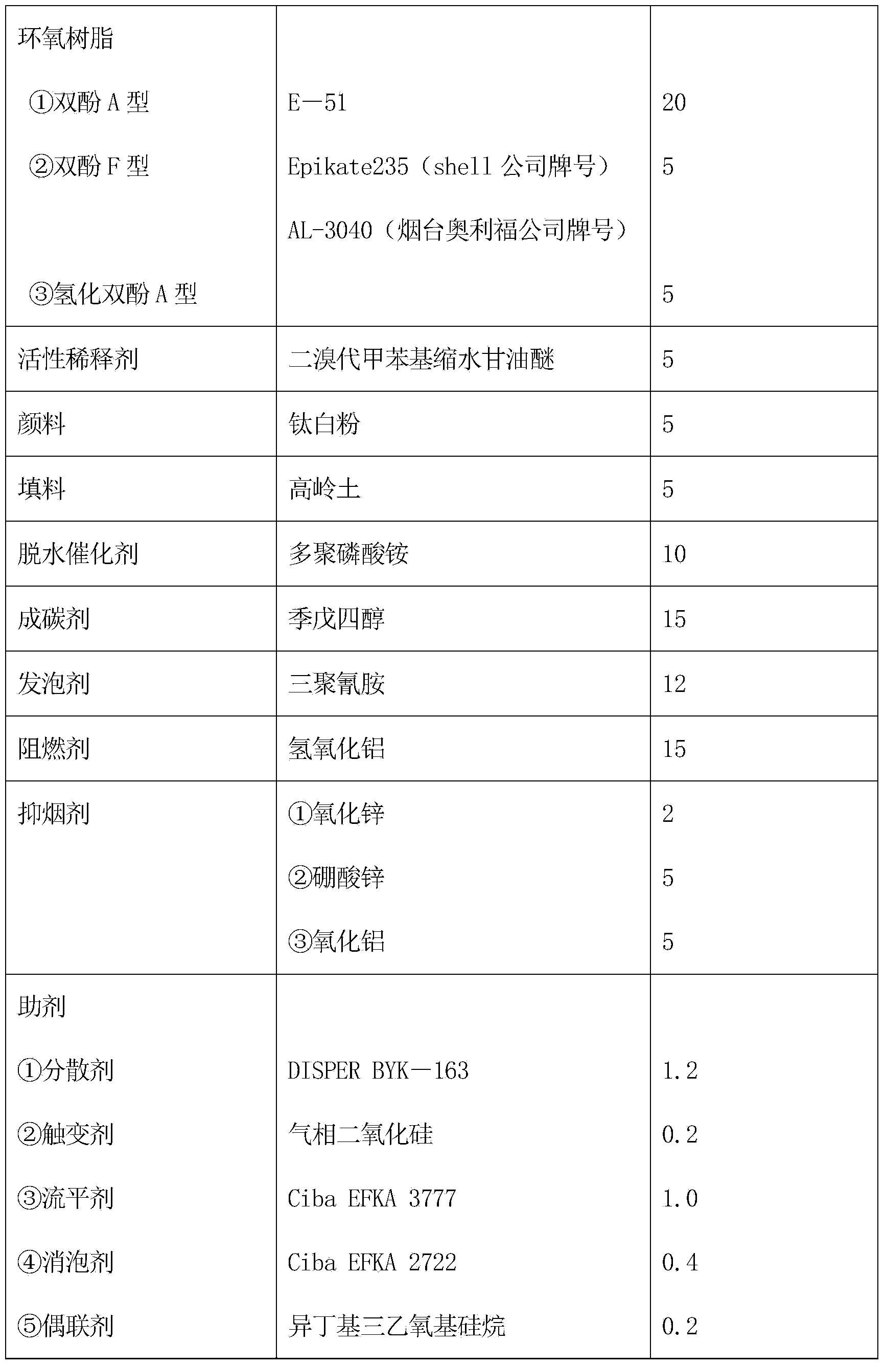
[0024] Component A of the present invention is composed of 15-35 parts of epoxy resin, 2-10 parts of active diluent, 5-15 parts of dehydration catalyst, 10-30 parts of char-forming agent, 5-20 parts of foaming agent, flame retardant 15-35 parts, 5-15 parts of smoke suppressant, 10-30 parts of pigment and filler, 2-10 parts of additives, the specific formula is shown in Table 1.

[0025] Table 1

[0026]

[0027]

[0028] ② Preparation method

[0029] Add in order in the dispersion tank: epoxy resin, active diluent, additives, pigments and fillers, dehydration catalyst, char-forming agent, foaming agent, flame retardant and smoke suppressant, and stir for about 30 minutes with a high-speed disperser , stand at room temperature for 1 to 2 hours, then jog and stir for 30 minutes, and stand for 24 hours to obtain component A, which is stored for later use.

[00...

Embodiment 2~4

[0041] Embodiment 2~4 prepares fireproof coating 2~4

[0042] (1) See Table 3 for the formula of component A of Examples 2-4.

[0043] table 3

[0044]

[0045]

[0046]

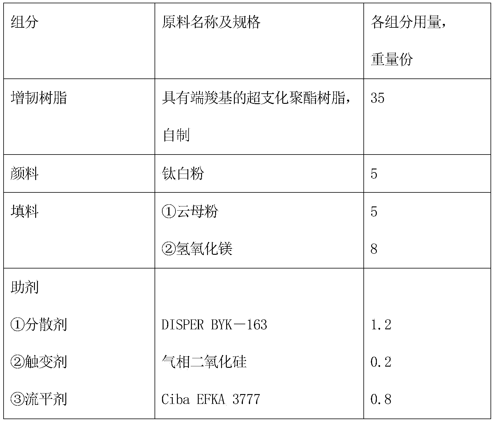
[0047] (2) See Table 4 for the formulations of the components in Examples 2 to 4B.

[0048] Table 4

[0049]

[0050] Annotate: the preparation method of the hyperbranched polyester resin with terminal carboxyl group is identical with embodiment 1.

Embodiment 2

[0052] Component C of Example 2 is ketimine (DT134, brand name of Feicheng Deyuan Chemical Company);


PUM

PropertyMeasurementUnit
thicknessaaaaaaaaaa

Abstract

The invention relates to a fire retardant coating for a steel structure surface of a nuclear power plant. The fire retardant coating consists of components A, B and C at a weight ratio of (4-6): 1: 1, wherein the component A is a mixture composed of 15-35 parts of epoxy resin, 2-10 parts of reactive diluent, 5-15 parts of dehydration catalyst, 10-30 parts of carbonizing agent, 5-20 parts of foaming agent, 15-35 parts of fire retardant, 5-15 parts of smoke inhibitor, 10-30 parts of pigment and filler and 2-10 parts of auxiliaries; the component B is a mixture composed of 10-50 parts of toughened resin, 10-30 parts of pigment and filler and 2-10 parts of auxiliaries; the C component is an amine curing agent; and the toughened resin in the component B is hyper-branched polyester resin with a terminal carboxyl group. The fire retardant coating disclosed by the invention is more excellent than a normal intumescence fire retardant coating in binding strength, freezing and thawing cycle resistance, acid and base resistance, and fire retardant limit, and is specifically up to fire resistance requirements of the steel structure surface of the nuclear power plant.

Description

technical field [0001] The invention relates to a fireproof coating on the surface of a nuclear power plant steel structure. Background technique [0002] The construction of nuclear power plants has entered a broad development space in recent years. The surface coating of steel structures in nuclear power plants not only needs to have radiation resistance and medium resistance, but also requires good fire resistance. Due to the non-combustibility of the steel structure itself, the fire protection and heat insulation protection of the steel structure is often ignored. The steel material generally only has a fire resistance limit of 15 minutes under direct burning by a high-temperature flame, and will quickly lose its bearing capacity. Under the action of temperature in a fire, the strength of a steel structure is a function of temperature. When the temperature of the structure reaches 300, 500, and 600°C, its strength decreases by 1 / 3, 1 / 2, and 2 / 3 respectively, and the mec...

Claims


Application Information

Patent Timeline
Patent Type & Authority Applications(China)
IPC IPC(8): C09D163/00C09D167/00C09D5/18C09D7/12
Inventor 陆文明王李军周如东李文凯王留方朱亚君赵宝华
Owner CHINA NAT OFFSHORE OIL CORP
Learn More