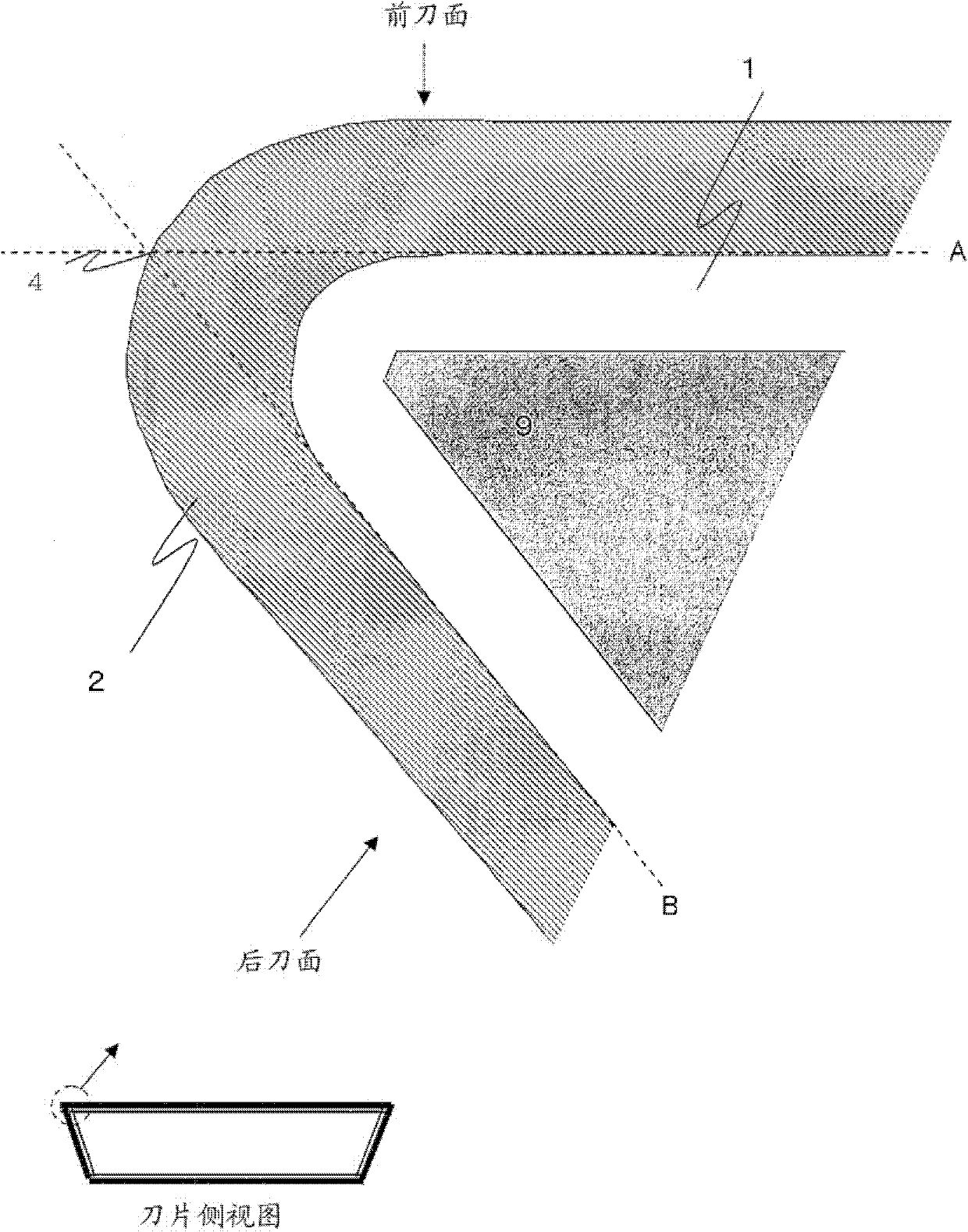
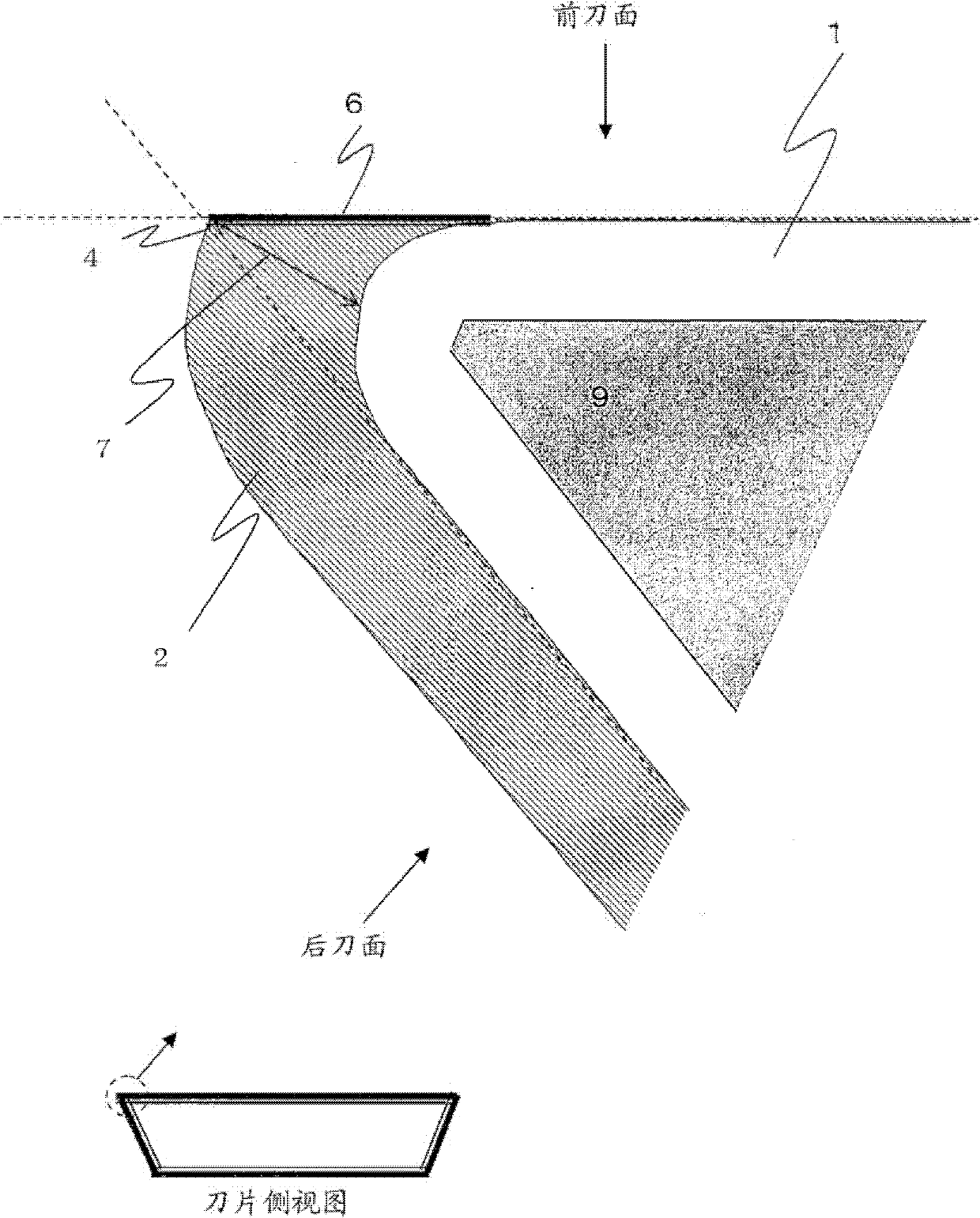
Cutting tool covered with diamond
A cutting tool and diamond technology, applied in the field of diamond-coated cutting tools, can solve the problems of difficulty in forming cutting edges, reduced machining accuracy, and short service life, and achieve improved lubricity and chip discharge, reduced frictional resistance, and full durability. abrasive effect
- Summary
- Abstract
- Description
- Claims
- Application Information
AI Technical Summary
Problems solved by technology
Method used
Image
Examples
Embodiment 1
[0076] (Laser processing rake face only)
[0077]As raw material powders, WC powder, TiC powder, TaC powder, NbC powder and Co powder each having an average particle size of 1 to 3 μm were prepared, and these raw material powders were blended into the compounding composition shown in Table 1, and wet mixed with a ball mill for 96 hours. , after drying, it is formed into a compact by stamping with a pressure of 100MPa, and the compact is sintered under the condition of maintaining a temperature of 1400°C for 1 hour in a vacuum of 6Pa, and the grinding process is performed, and the rake face of the cutting edge is mirror-finished. Cemented carbide substrates 1 to 10 each made of WC-based cemented carbide and having an insert shape according to ISO standard SPGN120308 were thus manufactured.
[0078] (a) Put the above-mentioned cemented carbide substrates 1-10 into a CVD apparatus. First, under the conditions shown in Table 2, vapor-deposit on the cutting edge, rake face, and fla...
Embodiment 2
[0128] (laser processing rake face and flank face)
[0129](a) Assemble the cemented carbide substrate having the crystalline diamond layer formed in Example 1 and the alternately laminated film by vapor deposition in a laser processing device, drive the laser light source of ultraviolet laser (wavelength: 262nm), and make the focusing lens Move along the optical axis direction of the ultraviolet laser, focus the ultraviolet laser at a position overlapping the center of the sample stage, then move the sample stage, and irradiate the ultraviolet laser on the rake face other than the cutting edge and the flank face, scan the laser with a galvano scanner to remove the alternately laminated film on the surface of the rake face and flank face other than the cutting edge,
[0130] (b) On the cutting edge, the crystalline diamond layer and the alternately laminated film shown in Table 10 are coated, and the surface layer on the rake face side and the surface layer on the flank side o...
Embodiment 3
[0163] (end mill)
[0164] As raw material powders, WC powder, TiC powder, TaC powder, NbC powder and Co powder each having an average particle diameter of 1 to 3 μm were prepared, and these raw material powders were blended into the compounding composition shown in Table 1, and wet mixed with a ball mill for 96 hours, After drying, it was pressed into a green compact with a pressure of 100 MPa, and the green compact was sintered under the condition of maintaining a temperature of 1400° C. for 1 hour in a vacuum of 6 Pa to form a round rod sintered body with a diameter of 13 mm for tool base formation. Processing From the round bar sintered body, a WC-based cemented carbide tool base (end mill) having a cutting edge with a diameter x length of 10 mm x 22 mm and a helix angle of 10 degrees in the shape of a four-edged square was manufactured, respectively. 1 to 10.
[0165] Next, the surfaces of these cemented carbide substrates (end mills) 1 to 15 are ultrasonically cleaned i...
PUM
 Abstract
Description
Claims
Application Information
 - R&D
- Intellectual Property
- Life Sciences
- Materials
- Tech Scout
- Unparalleled Data Quality
- Higher Quality Content
- 60% Fewer Hallucinations
Browse by: Latest US Patents, China's latest patents, Technical Efficacy Thesaurus, Application Domain, Technology Topic, Popular Technical Reports.
© 2025 PatSnap. All rights reserved.Legal|Privacy policy|Modern Slavery Act Transparency Statement|Sitemap|About US| Contact US: help@patsnap.com


