Method for producing electrochemical device
a technology of electrochemical devices and spiral electrodes, applied in the direction of wound/folded electrode electrodes, sustainable manufacturing/processing, non-aqueous electrolyte cells, etc., can solve the problems of film distortion, internal short circuit, and the electrode body thus produced cannot be easily removed from the winding shaft, so as to improve the productivity of the electrochemical device, improve the safety, and reduce the manufacturing failure of spiral electrode bodies.
- Summary
- Abstract
- Description
- Claims
- Application Information
AI Technical Summary
Benefits of technology
Problems solved by technology
Method used
Image
Examples
embodiment 1
[0027]First, an electrochemical device of the present invention will be described. A separator used for the electrochemical device of the present invention includes a first porous layer composed mainly of a thermoplastic resin and a second porous layer composed mainly of insulating particles with a heat-resistant temperature of 150° C. or higher. In the following, the first porous layer and the second porous layer are referred to as a porous layer (I) and a porous layer (II), respectively.
[0028]The porous layer (I) of the separator serves mainly to ensure a shutdown function. When the temperature of the electrochemical device of the present invention reaches the melting point or higher of the thermoplastic resin (referred to as a resin (A) in the following) that is the main component of the porous layer (I), the resin (A) of the porous layer (I) melts and fills the pores of the separator, and thus can effect a shutdown to interfere with the progress of an electrochemical reaction.
[0...
embodiment 2
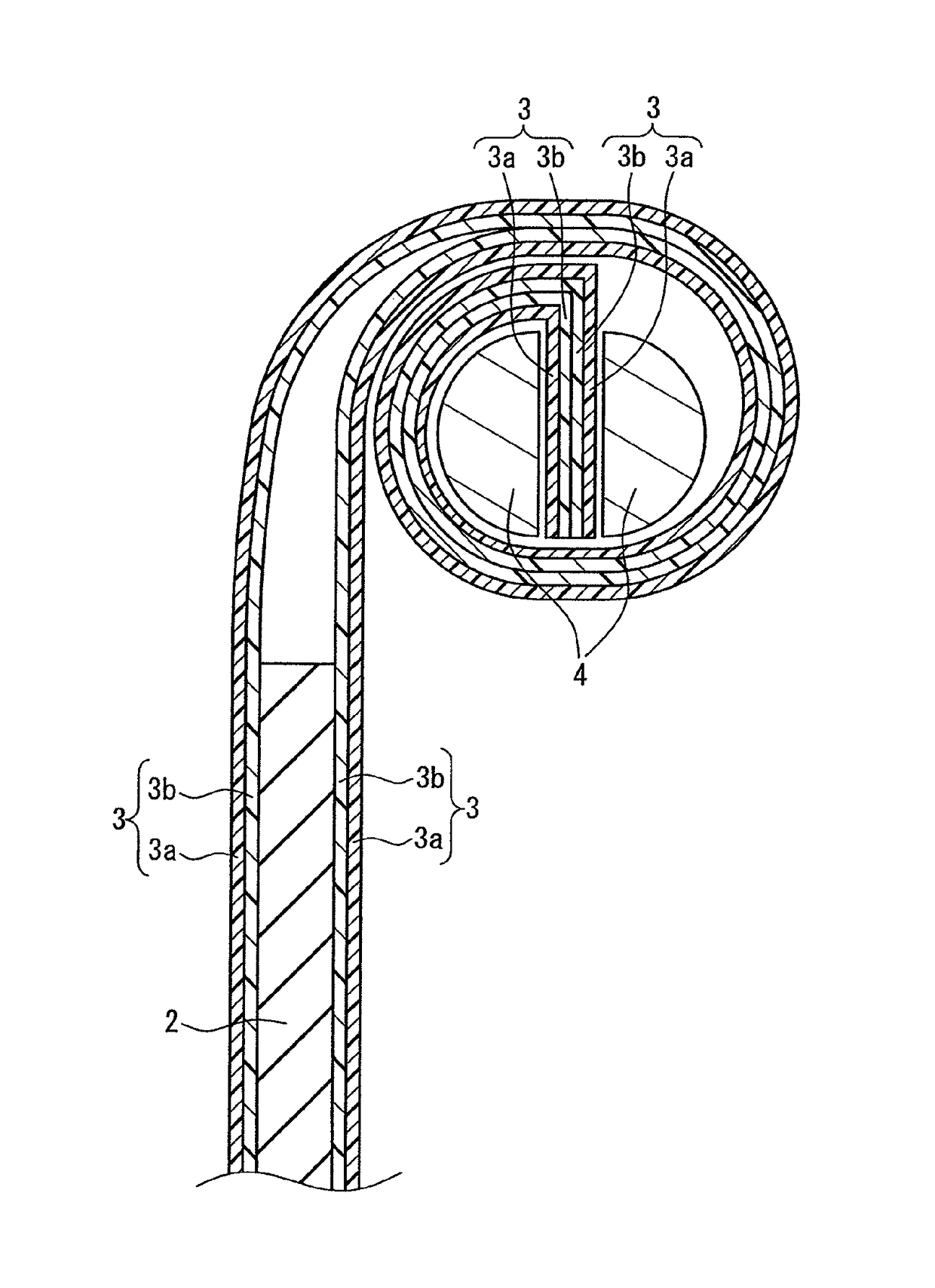
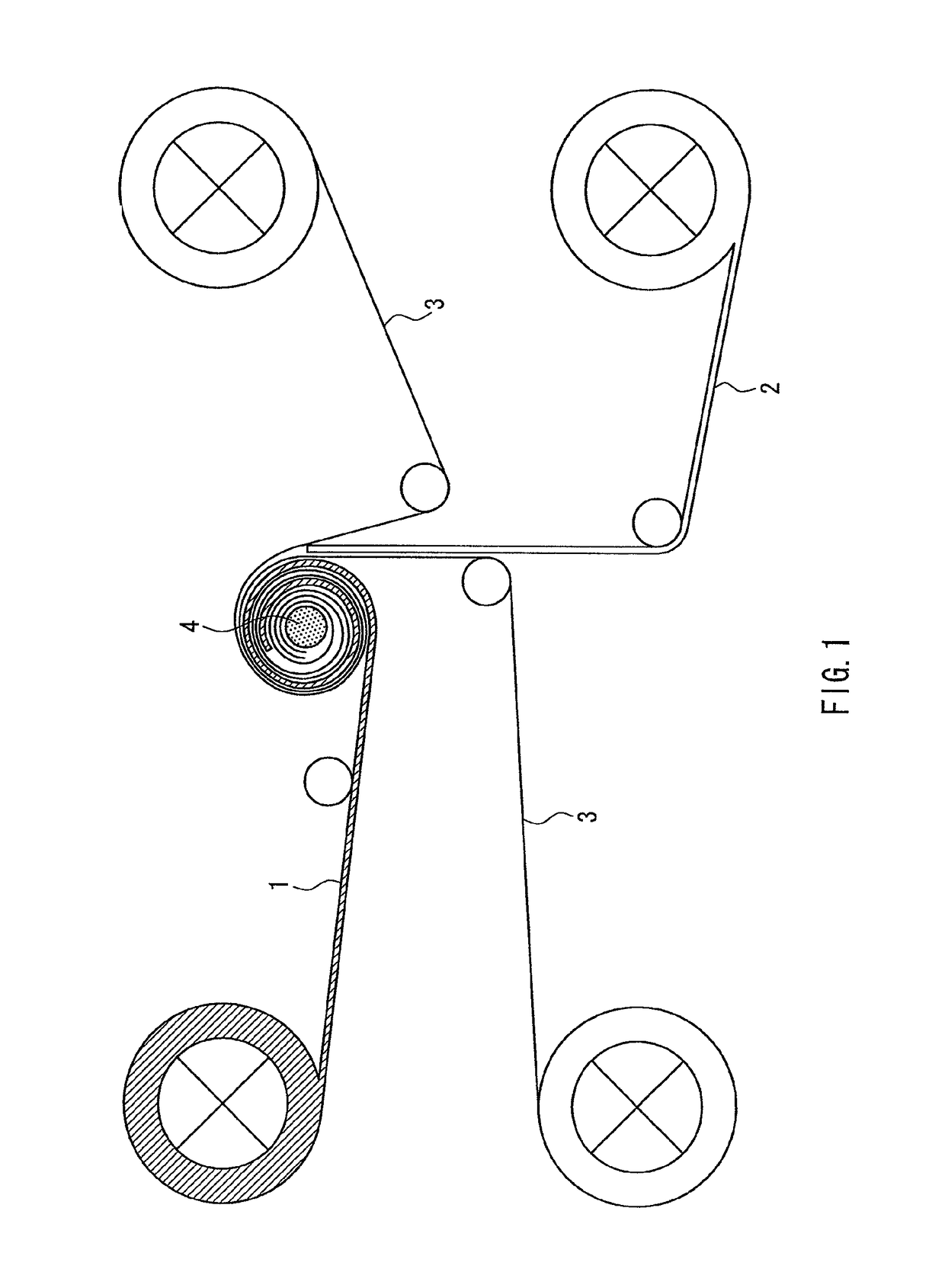
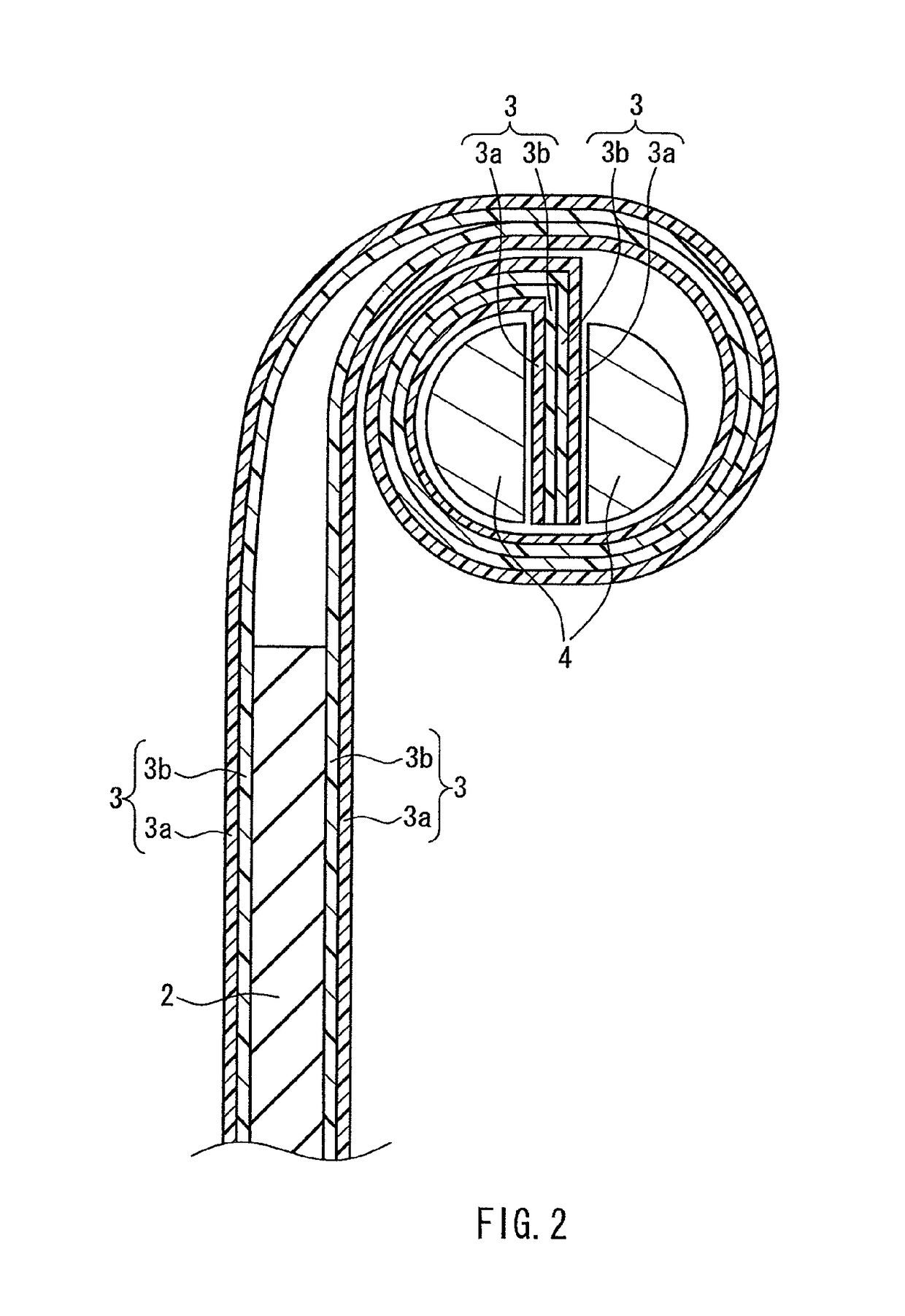
[0116]Next, a method for manufacturing an electrochemical device of the present invention will be described from the viewpoint different from Embodiment 1. The positive electrode and the negative electrode are stacked via the separator to form an electrode body. This electrode body is used for assembly of the electrochemical device without any change in shape. Alternatively, the separator is wrapped around a winding shaft, and then further wound with the positive electrode and the negative electrode to form a spiral electrode body, which is used for assembly of the electrochemical device. However, in the case of the separator having different friction coefficients on both sides, such as the separator including the porous layer (I) on one side and the porous layer (II) on the other side, the following problems are likely to arise during the production of the spiral electrode body. If winding is performed by arranging the separator with its higher friction coefficient side facing the ...
example 1
[0140]1000 g of alumina (filler) with an average particle size of 0.3 μm, 800 g of water, 200 g of isopropyl alcohol (IPA), and 375 g of a water / IPA solution of polyvinyl butyral (binder) having a solid content of 15% were put in a container, and stirred with a Three-One Motor for 1 hour and dispersed, resulting in a uniform slurry (slurry 1). A PET nonwoven fabric with a thickness of 12 μm and a weight of 8 g / m2 was immersed in and removed from the slurry 1, and thus the slurry 1 was applied to the nonwoven fabric. This nonwoven fabric was allowed to pass through a predetermined gap and then dried, thereby providing a porous film (porous layer (II)) with a thickness of 20 μm. A water dispersion of a PE powder (with an average particle size of 1 μm and a solid concentration of 40%) was applied to one surface of the porous film using a blade coater and then dried, so that a PE fine particle layer (porous layer (I)) was formed to have a thickness of 5 μm. In this manner, a separator w...
PUM
| Property | Measurement | Unit |
|---|---|---|
| heat-resistant temperature | aaaaa | aaaaa |
| average particle size | aaaaa | aaaaa |
| melt viscosity | aaaaa | aaaaa |
Abstract
Description
Claims
Application Information
 - R&D
- Intellectual Property
- Life Sciences
- Materials
- Tech Scout
- Unparalleled Data Quality
- Higher Quality Content
- 60% Fewer Hallucinations
Browse by: Latest US Patents, China's latest patents, Technical Efficacy Thesaurus, Application Domain, Technology Topic, Popular Technical Reports.
© 2025 PatSnap. All rights reserved.Legal|Privacy policy|Modern Slavery Act Transparency Statement|Sitemap|About US| Contact US: help@patsnap.com


