
Electrocatalyst for ethanol oxidation and direct ethanol fuel cell using the same

a fuel cell and electrocatalyst technology, applied in the field of fuel cells, can solve the problems of inability to completely eliminate the formation of carbon monoxide (co) or other impurities in the hydrogen fuel gas, and the fuel cell that uses pefc cannot be effectively utilized by the public, etc., to achieve the effect of reducing overvoltage, improving output current density, and reducing toxicity

Inactive Publication Date: 2011-06-14
RICOH KK
View PDF15 Cites 3 Cited by
  • Summary
  • Abstract
  • Description
  • Claims
  • Application Information

AI Technical Summary

Benefits of technology

[0071]Thereupon, the general object of the present invention is to provide a novel and useful fuel cell that eliminates the foregoing problems.
[0072]Another and more specific object of the present invention is to provide a direct ethanol fuel cell capable of providing higher electromotive force (EMF) and higher output by using an electrocatalyst that can reduce the overvoltage and increase the current density.

Problems solved by technology

However, such a fuel cell that uses PEFC cannot be utilized effectively by the public unless infrastructure for hydrogen gas fuel supply is deployed.
Further, there are many problems to be solved in the technology of PEFC that uses hydrogen gas as a fuel in relation to the storage and transport of the hydrogen fuel and the technology of handling the hydrogen fuel safely.
Because of this, it is now recognized that the use of hydrogen fuel is not suitable for the electric power supply of small electronic apparatuses or portable electronic apparatuses of personal use.
In the fuel cell of the type that reforms such hydrocarbon fuel, however, it is generally not possible to completely eliminate the formation of carbon monoxide (CO) or other impurities from the hydrogen fuel gas during the reformation process of the raw fuel.
Such impurities, particularly CO, cause damaging effect to the function of the fuel cell.
It is recognized that CO causes deactivation of platinum catalyst and causes damages on the function of the anode electrocatalyst of the fuel cell, and hence the power generation performance of the fuel cell.
As noted above, it has been a major subject in the conventional fuel cell technology to reduce the poisoning of platinum catalyst caused by CO, while this problem becomes a particularly serious problem in the case of using a reformed gas fuel in place of a hydrogen gas.
However, there still remain various problems not understood, such as migration of the CO molecules on the adsorbed surface, change of the electron state of the platinum surface covered with CO, and associated change of the coverage rate of CO, even in the case of such a surface reaction taking place in the catalyst metal-gas phase system.
Thus, conventional technology cannot provide a quantitative solution to these various phenomena, and there exists no universal technology capable of eliminating the problem of poisoning of platinum catalyst.
Although there are various advantages in a direct methanol fuel cell, there exists also a problem in that the anode oxidation reaction of methanol provides a large overvoltage.
In the case of a direct methanol fuel cell, on the other hand, methanol oxidation becomes a major bottleneck, and the problem of decrease of output is not avoidable.
Further, toxicity of methanol can not only harm the human health but also threaten the human life.
However, such fuel cells cannot provide the output performance superior to the one obtained in the case methanol is used.
Nevertheless, no satisfactory ethanol oxidation has been achieved even in the case the alloy of Pt and Ru is used for the electrode.
Nevertheless, the handling of hydrogen fuel cell is complex as noted before, and a hydrogen fuel cell is inappropriate for the power supply of personal usage.
However, methanol has a problem of large overvoltage at the time of the anode oxidation in any of the cases when it is used alone or when it is used in the form mixed with water.
Further, the current that can be taken out from the fuel cell does not reach the value obtained in the case of using hydrogen.
In addition to this, ethanol or dimethylether is thought as promising candidates, but these fuels cannot provide the anode oxidation characteristic that exceeds the case in which methanol is used.
Thus, the anode oxidation reaction caused in the case of using a fuel of alcohol or alcohol solution has a complicated aspect and cannot be explained by a simple surface reaction taking place between the catalyst metal and gas phase.
However, there is no established theory accepted by those persons skilled in the art.
In the case of the direct anode oxidation of alcohol, however, the reaction becomes a liquid phase reaction taking place in a solution, irrespective of whether water is involved or not, and various molecular species can become the obstacle of the anode oxidation catalysis, in addition to CO.
It has been understood that the oxidation of methanol becomes the bottleneck because the carbon monoxide formed during the process of electrode oxidation of methanol is adsorbed on the electrode and poisoning is caused in the electrocatalyst including platinum as a result.
Even in this case, however, the reaction at the anode is still a bottleneck as compared with the oxygen reduction reaction taking place at the cathode.
As ethanol includes two carbon atoms in the structure, the complexity of the anode oxidation reaction process would be incomparable with the foregoing anode oxidation reaction process for methanol.
Thus, the technology of direct ethanol fuel cell has not reached the level of practical use yet, apart from its theoretical possibility.
However, there has been no known electrocatalyst that can reduce the overvoltage of the reaction and simultaneously increase the current density while using ethanol for the fuel.

Method used


Image

  • Electrocatalyst for ethanol oxidation and direct ethanol fuel cell using the same
  • Electrocatalyst for ethanol oxidation and direct ethanol fuel cell using the same
  • Electrocatalyst for ethanol oxidation and direct ethanol fuel cell using the same

Examples


first embodiment

[0090]First, the structure of the fuel cell of the present invention will be explained in relation to the construction and operation of the present invention.

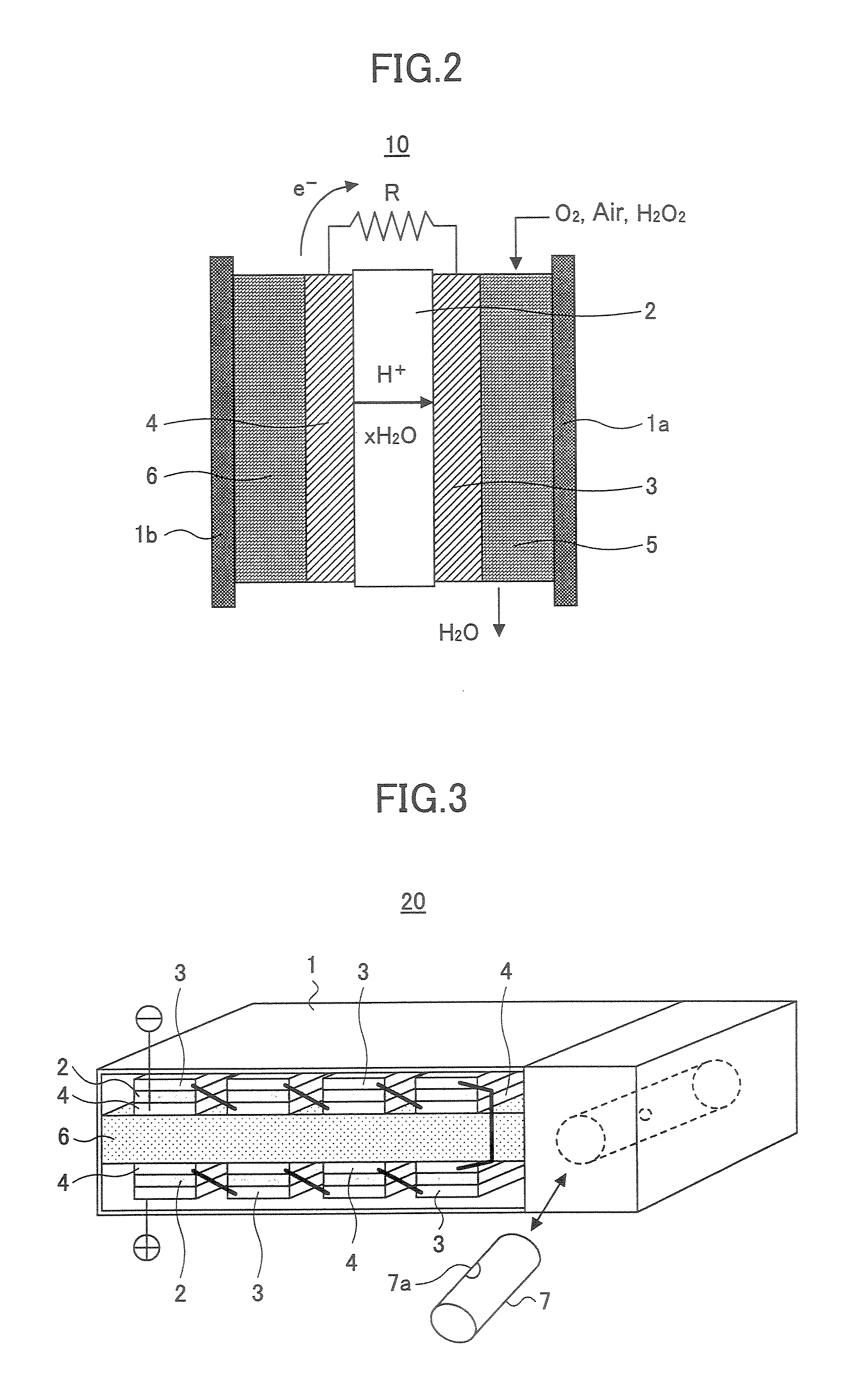
[0091]FIG. 2 is a schematic diagram of a single cell structure constituting a single cell element of a general fuel cell, wherein the cell structure of FIG. 2 is used also in the present invention. Thus, FIG. 2 shows the construction of a direct ethanol polymer electrolyte fuel cell (PEFC) 10 according to an embodiment of the present invention.

[0092]Referring to FIG. 2, the PEFC 10 of the present invention includes an ion exchange membrane 2, a cathode 3 that supports the ion exchange membrane 2 and an anode 4 in a housing represented by the numerals 1a and 1b, wherein there are further provided with an oxidizer channel 5 and a liquid fuel storage part 6 at the respective outer sides of the cathode 3 and the anode 4.

[0093]Any of anion conduction type and cation conduction type can be used for the ion exchange membrane 2, wherei...

second embodiment

[0105]FIG. 3 is a schematic diagram showing the construction of a PEFC 20 according to a second embodiment of the present invention.

[0106]Referring to FIG. 3, it can be seen that the PEFC 20 of the present embodiment has a generally flat rectangular shape.

[0107]Within the PEFC 20, there is formed a fuel supply path 6 so as to divide the interior of the PEFC 20 to an upper part and a lower part, and there is further provided a storage part of the liquid fuel in the form of a cylindrical container 7.

[0108]It should be noted that the container 7 is provided detachably to the body of the PEFC 20 and the fuel stored in the container 7 is supplied to the fuel supply path 6 through a small hole 7a formed in the sidewall of the container 7. The hole 7a is closed by a seal (not shown) in the state before the container 7 is mounted inside the body of the fuel cell and the ethanol fuel is sealed in the container 7. It should be noted that the small hole 7a is formed in the position where the s...

example 10

[0131]Hereinafter, the result of characterization of the multicomponent alloy catalyst of the present invention will be shown for the composition and structure as Example 10. In the present embodiment, a multicomponent alloy formed by sputtering is presented as a typical example.

[0132]FIG. 5 shows the result of analysis of the crystal structure of the catalyst layer by XRD (X-ray diffraction) method.

[0133]Referring to FIG. 5, it can be seen that the catalyst layer of the Pt show a diffraction peak of fcc (face centered cubic) structure. Although not illustrated in FIG. 5, similar XRD analysis reveals that the catalyst layer of the Ru has an hcp (hexagonal closest packing) structure. Further, it was confirmed that the catalyst layer of the W has a ccp (cube closest packing) structure.

[0134]In the case of the Pt—Ru binary catalyst layer, the peak of Pt and Ru are basically observed although the peak position is shifted slightly from the characteristic peak of the simple metal. Thereby...


PUM

PropertyMeasurementUnit
temperatureaaaaaaaaaa
thicknessaaaaaaaaaa
pressureaaaaaaaaaa

Abstract

An electrocatalyst for ethanol oxidization includes an elemental mixture containing platinum and ruthenium and at least one element, wherein the foregoing at least one element is selected from the group of tungsten, tin, molybdenum, copper, gold, manganese, and vanadium.

Description

CROSS-REFERENCE TO RELATED APPLICATIONS[0001]This application is a continuation of U.S. patent application Ser. No. 10 / 682,120, filed on Oct. 10, 2003 now abandoned, which claims priority to Japanese Patent Application No. 2003-344727, filed on Oct. 2, 2003, and Japanese Patent Application No. 2002-298138, filed on Oct. 11, 2002.BACKGROUND OF THE INVENTION[0002]The present invention generally relates to fuel cells and more particularly to a novel anode electrocatalyst for use in a fuel cell. The present invention particularly relates to a high-output fuel cell of the type that supplies fuel containing ethanol as a principal ingredient directly to an anode and to the electrocatalyst that can efficiently oxidize such a fuel containing ethanol as the principal ingredient and supplied directly to the anode. Further, the present invention relates to an electronic device that uses such a fuel cell.[0003]The fuel cell that uses a fuel of hydrogen gas can provide a high output power density...

Claims


Application Information

Patent Timeline
Patent Type & Authority Patents(United States)
IPC IPC(8): H01M8/10H01M4/92C22C5/04B01J23/56B01J23/62B01J23/652B01J23/89B01J37/34C23C14/16C23C14/34H01M4/86H01M4/88H01M4/90H01M8/24
CPCB01J23/56B01J23/6527C22C5/04C23C14/165C23C14/3464H01M4/8621H01M4/8652H01M4/8885H01M4/9041H01M4/921H01M8/1013H01M8/2455B01J23/626Y02E60/522B01J23/8926B01J37/347Y02E60/50
Inventor UCHIDA, ISAMUUMEDA, MINORUOJIMA, HIROYUKI
Owner RICOH KK
Learn More