Multi-layer capacitive transducer
a capacitive transducer and multi-layer technology, applied in capacitors with temperature varied dielectrics, capacitors with electrode area variation, instruments, etc., can solve the problems of sudden bulging of springs sideways, inability to use rotor plate skins with a thickness, and insufficient thickness to provide optimal resistance to sideways rocking. , to achieve the effect of eliminating errors, easy measurement, and increasing alignment accuracy
- Summary
- Abstract
- Description
- Claims
- Application Information
AI Technical Summary
Benefits of technology
Problems solved by technology
Method used
Image
Examples
first embodiment
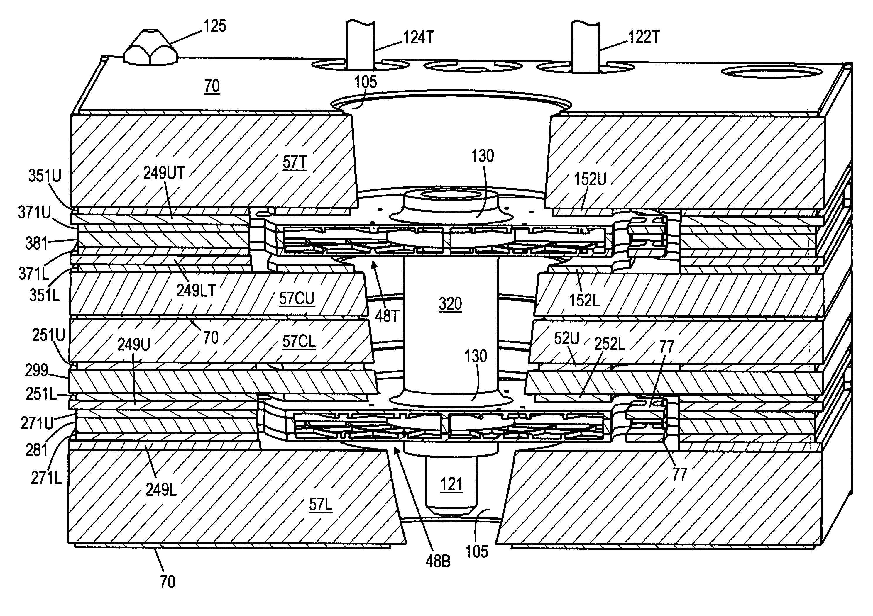
[0091]Rotor core layer 281 (FIG. 17) has rotor core 90 and tabs 89 which are the same as in the Rotor core frame 286 has the same features as rotor plate skin layer 276.
[0092]Pickup electrode layer 251L (FIG. 18) is similar to lower drive electrode layer 51L of the first embodiment. Since the rotor plates are grounded and isolated spring anchors are not required, supports 55L are not isolated, and are incorporated into frame 256L. Pickup electrode 252L is the same shape as drive electrode 52L, but is located above rotor plate 48B. Trace 253L connects electrode 252L to pad 254L, which is connected to front center electrical interconnect pin 123B (FIG. 4). Hole 102 for pin 123B is not shown in pad 254L in FIG. 18, as holes 102 are drilled through the entire transducer after the final assembly. As in the first embodiment, if the substrate material is G-10 printed circuit board laminate, layer 251L, as well as shields 70 and other stator (non-rotor) electrodes are preferably made of co...
third embodiment
[0099]A third embodiment, optimized for significantly higher loads, will now be described. The specified dimensions are for a transducer with a load capacity of 1000 grams. Since this is currently significantly greater than the force that can be generated by electrostatic actuation, this embodiment is shown without the electrostatic actuation drive electrodes. The top section includes the drive electrode, pickup electrode, and rotor plate, which may function directly as a target electrode for position sensing (which the stiffness of the springs converts to force sensing), or a separate unstressed target electrode may be added in addition to the rotor plate, for better linearity. The bottom section includes the rotor plate layer without position sensing electrodes, to constrain the motion to the vertical axis only, so that off center or off axis loads do not result in excessive errors in the measurements. Position sensing electrodes could be included in the lower section as well, whi...
second embodiment
[0105]Upper gap spacer 660 (FIG. 31), positioned immediately above rotor plate layer 650, provides space for target electrode 642 and rotor plate 652 to move in the upwards direction. Space in the downwards direction is provided by spacer 630. Spacer 660 includes frame 661, with inner opening 666. The shape of inner opening 666 is selected so that frame 661 provides optimal support to rotor plate layer 650, without interfering in the motion of springs 659 or plate 652. Alignment holes 500E are used in the assembly process. Spacer 660 is preferably constructed of metal, such as brass, and may be 0.016 inch thick. Lower gap spacer 630 may be constructed of G-10 printed circuit board substrate material, and may have a thickness of about 0.01 inch. As shown in FIG. 28, spacer 630 must be constructed of an electrically insulating material to prevent shorting the pickup signal on trace 623 and pad 624 to ground. If isolation channels such as those included in spacer 349L of the second emb...
PUM
 Abstract
Description
Claims
Application Information
 - R&D
- Intellectual Property
- Life Sciences
- Materials
- Tech Scout
- Unparalleled Data Quality
- Higher Quality Content
- 60% Fewer Hallucinations
Browse by: Latest US Patents, China's latest patents, Technical Efficacy Thesaurus, Application Domain, Technology Topic, Popular Technical Reports.
© 2025 PatSnap. All rights reserved.Legal|Privacy policy|Modern Slavery Act Transparency Statement|Sitemap|About US| Contact US: help@patsnap.com


