Integrated power circuits with distributed bonding and current flow
a power circuit and current flow technology, applied in the field of integrated power circuits, can solve the problems of preventing the implementation of this bonding-over-active-circuit concept, affecting the performance of the circuit, so as to enhance the dissipation of thermal energy and minimize the power delivery distance
- Summary
- Abstract
- Description
- Claims
- Application Information
AI Technical Summary
Benefits of technology
Problems solved by technology
Method used
Image
Examples
Embodiment Construction
[0035]The present invention is related to U.S. patent application Ser. No. 08 / 959,410, filed on 28 Oct. 1997 (Shen et al., “Integrated Circuit with Bonding Layer over Active Circuitry”, TI-24445); TI-31294, submitted on 7 Jul. 2000 (Shen et al., “Integrated Circuit with Bonding Layer over Active Circuitry”); and Ser. No. 09 / 458,593, filed on 10 Dec. 1999 (Zuniga et al., “System and Method for Bonding over Integrated Circuits”, TI-27502).
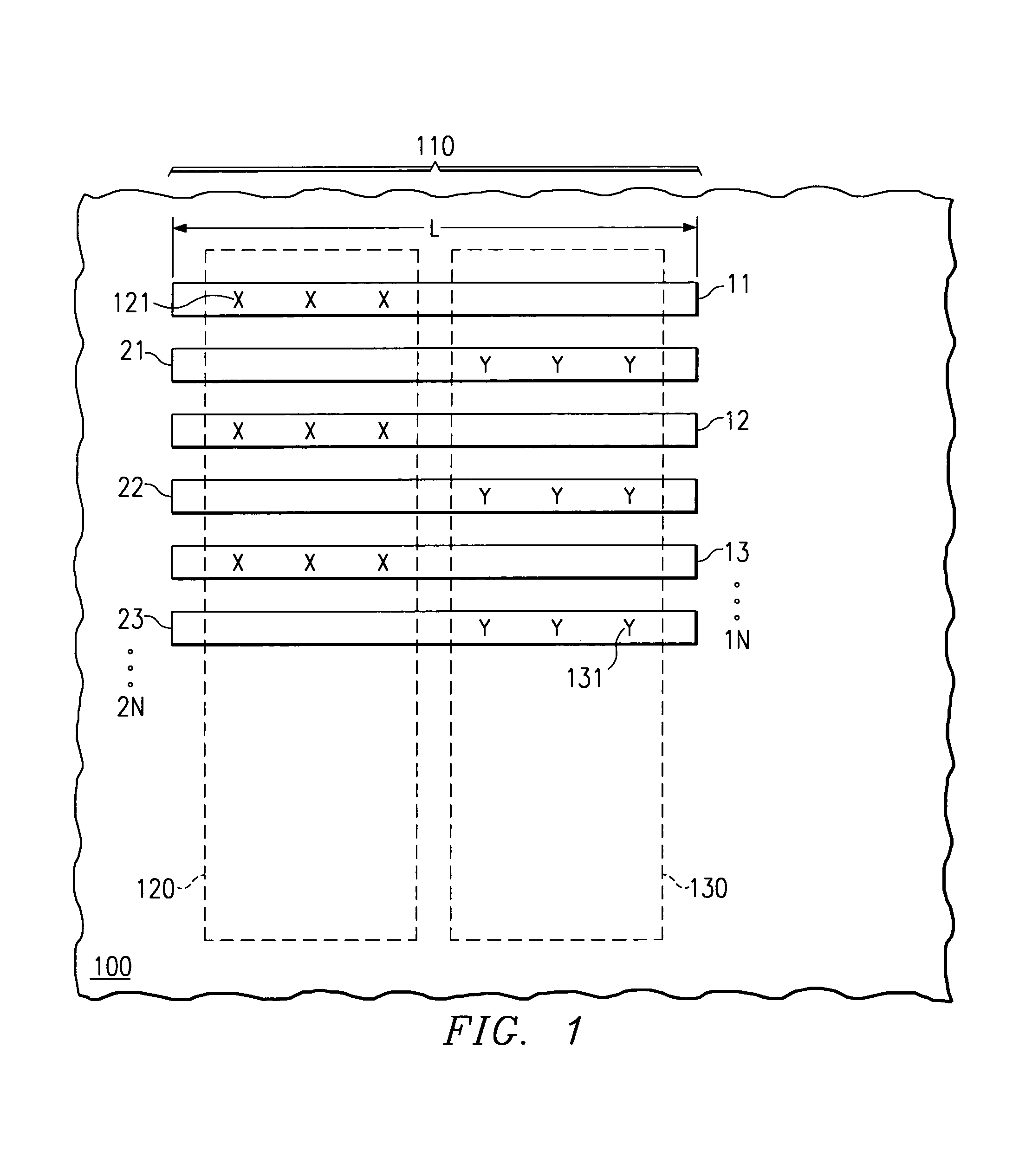
[0036]FIG. 1 illustrates a portion of a semiconductor integrated circuit (IC) chip 100 having a power transistor generally designated 110. This power transistor features a plurality of alternating regions for source and drain, which, by way of example, are arranged laterally in elongated strips and parallel to each other at a certain pitch. Each region is contacted by electrodes formed from a layer of metal, shown in FIG. 1 as parallel lines of length L and designated 11, 12, 13, . . . , 1N for the source electrodes, and 21, 22, 23, . . . , 2N for th...
PUM
 Abstract
Description
Claims
Application Information
 - R&D
- Intellectual Property
- Life Sciences
- Materials
- Tech Scout
- Unparalleled Data Quality
- Higher Quality Content
- 60% Fewer Hallucinations
Browse by: Latest US Patents, China's latest patents, Technical Efficacy Thesaurus, Application Domain, Technology Topic, Popular Technical Reports.
© 2025 PatSnap. All rights reserved.Legal|Privacy policy|Modern Slavery Act Transparency Statement|Sitemap|About US| Contact US: help@patsnap.com


