
Inject synchronous narrowband reproducible phase locked looped

a phase lock loop and synchronization technology, applied in the field of high-speed clock recovery circuits, can solve the problems of phase difference cannot be cancelled, cannot be integrated, and cannot be adjusted within a chip, so as to improve noise performance, improve frequency capture time of isnrpll circuits, and improve circuit performance.

Inactive Publication Date: 2005-08-02
HUAWEI TECH CO LTD
View PDF3 Cites 25 Cited by
  • Summary
  • Abstract
  • Description
  • Claims
  • Application Information

AI Technical Summary

Benefits of technology

[0011]In order to overcome the disadvantages of present ILPLL circuit, the invention provides an Injection Synchronization Narrowband Regenerative PLL (ISNRPLL) circuit, which is based on Injection Synchronization Narrowband Regenerative VCO (ISNRVCO). The ISNRPLL has all advantages of conventional ILPLL circuit, and is suitable to be integrated with depth-submicron digital CMOS technology. Moreover, the ISNRPLL can rapidly adjust phase relation between the input data and the output clock to implement a clock regeneration and auto-calibration with the input data.
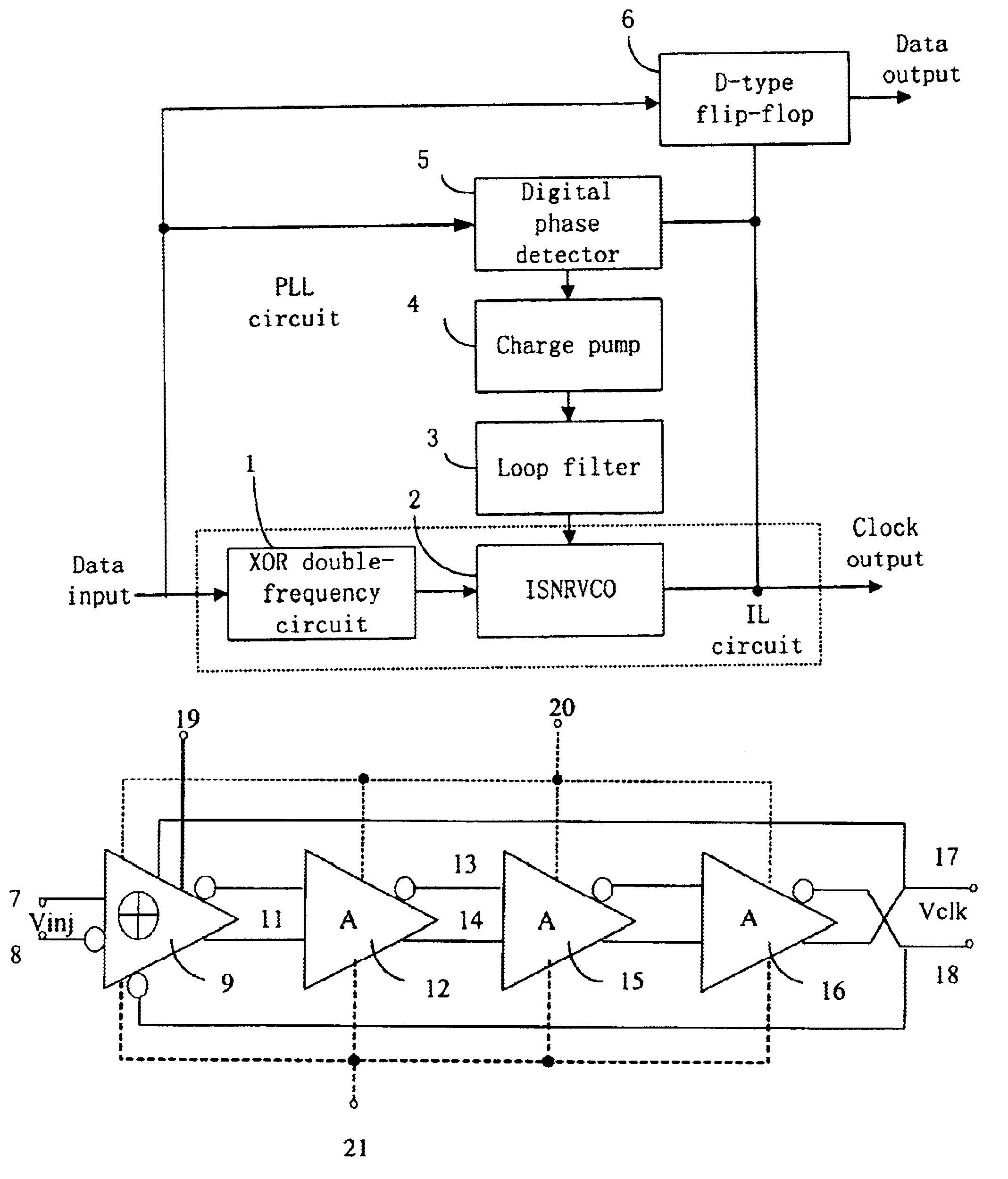
[0024]The ISNRVCO is the kernel part of the ISNRPLL of the invention. Phase difference and frequency difference information, which is produced by a digital phase-detector with bang-bang working mode, controls ISNRVCO through a low-pass section consisted of a charge pump and a loop filter. Requirement of the resonance circuit in an ISNRVCO is not high. The resonance circuit can be implemented by integrated inductance on a chip. Therefore, it is suitable for a variety of technologies, it needs only a few external components and it is not need external reference clock. Two parts: synchronous oscillator and phase-locked loop are interacted with each other. Therefore, performance of the circuit is raised greatly; such as capture range, capture time and phase noise etc. are all better than the conventional phase-locked loop circuit and can be used in GHz level high-speed clock recovery integrated circuit.
[0025]According to results of simulation, frequency capture range of an ISNRPLL circuit is greater than conventional two orders phase-locked loop in several ten times. Therefore, in some application, there is no need to set special frequency capture circuit. Simulation also shows that frequency capture time of an ISNRPLL circuit is improved in a greater degree. Noise analysis shows that at carrier frequency remote end and near end, noise performance is better.

Problems solved by technology

The disadvantages of passive filter circuit are as follow: it cannot be integrated, working frequency region is narrow, and it cannot be adjusted within a chip.
The disadvantages of synchronous oscillator circuit are as follow: phase difference cannot be cancelled, phase difference is related with frequency deviation, and noise performance of carrier frequency near end is worse.
The disadvantages of PLL circuit are as follow: the circuit is rather complex, capture range of itself is rather small, it is difficult to solve conflict of the noise bandwidth and the capture range, and the capture speed is rather slow.
Nevertheless, there are two disadvantages, which affect the implementation in a semiconductor chip.
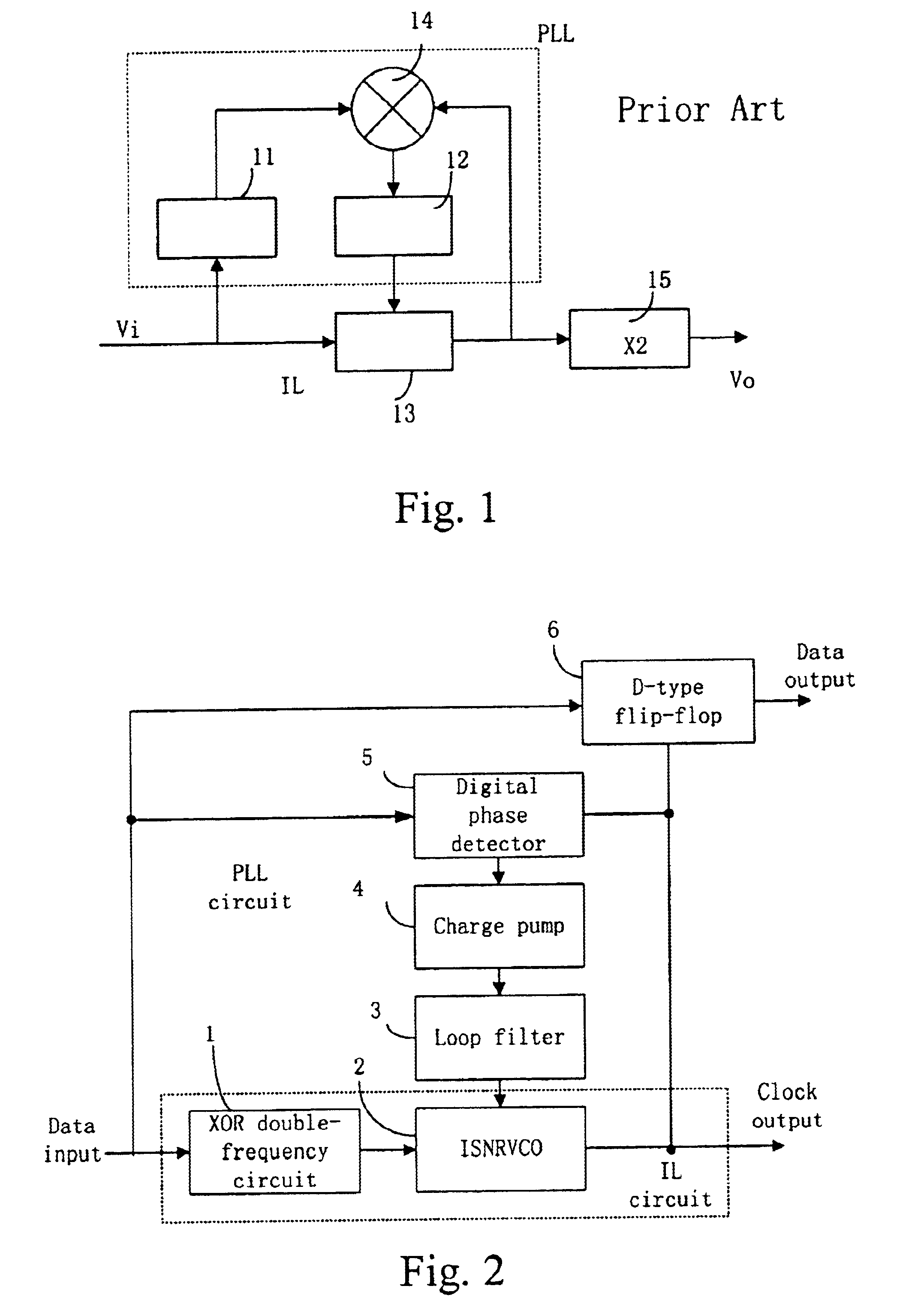
The two disadvantages are:(1) when a clock frequency is an ultrahigh frequency, there are some difficulties to implement on a chip;(2) the present circuit cannot better adjust the phase difference between the input data Vi and the output clock.
The double frequency circuit brings another phase deviation, which is difficult to control.

Method used


Image

  • Inject synchronous narrowband reproducible phase locked looped
  • Inject synchronous narrowband reproducible phase locked looped
  • Inject synchronous narrowband reproducible phase locked looped

Examples


Embodiment Construction

[0032]FIG. 2 shows an ISNRPLL circuit principle block diagram. The ISNRPLL circuit includes an exclusive-OR double-frequency circuit 1, an ISNRVCO 2, a digital phase detector 5 working with bang-bang mode, a charge pump 4, a loop filter 3 and a D-type flip-flop 6. The exclusive-OR double-frequency circuit 1 and the ISNRVCO 2 constitute the injection locked loop (IL circuit). The bang-bang digital phase detector 5, the charge pump 4 and loop filter 3 constitute the PLL (PLL circuit). The D-type flip-flop 6 is used for data decision output. A phase difference and frequency difference information, produced by the digital phase detector 5, controls the ISNRVCO 2 through a low-pass sector consisted of charge pump 4 and loop filter 3.

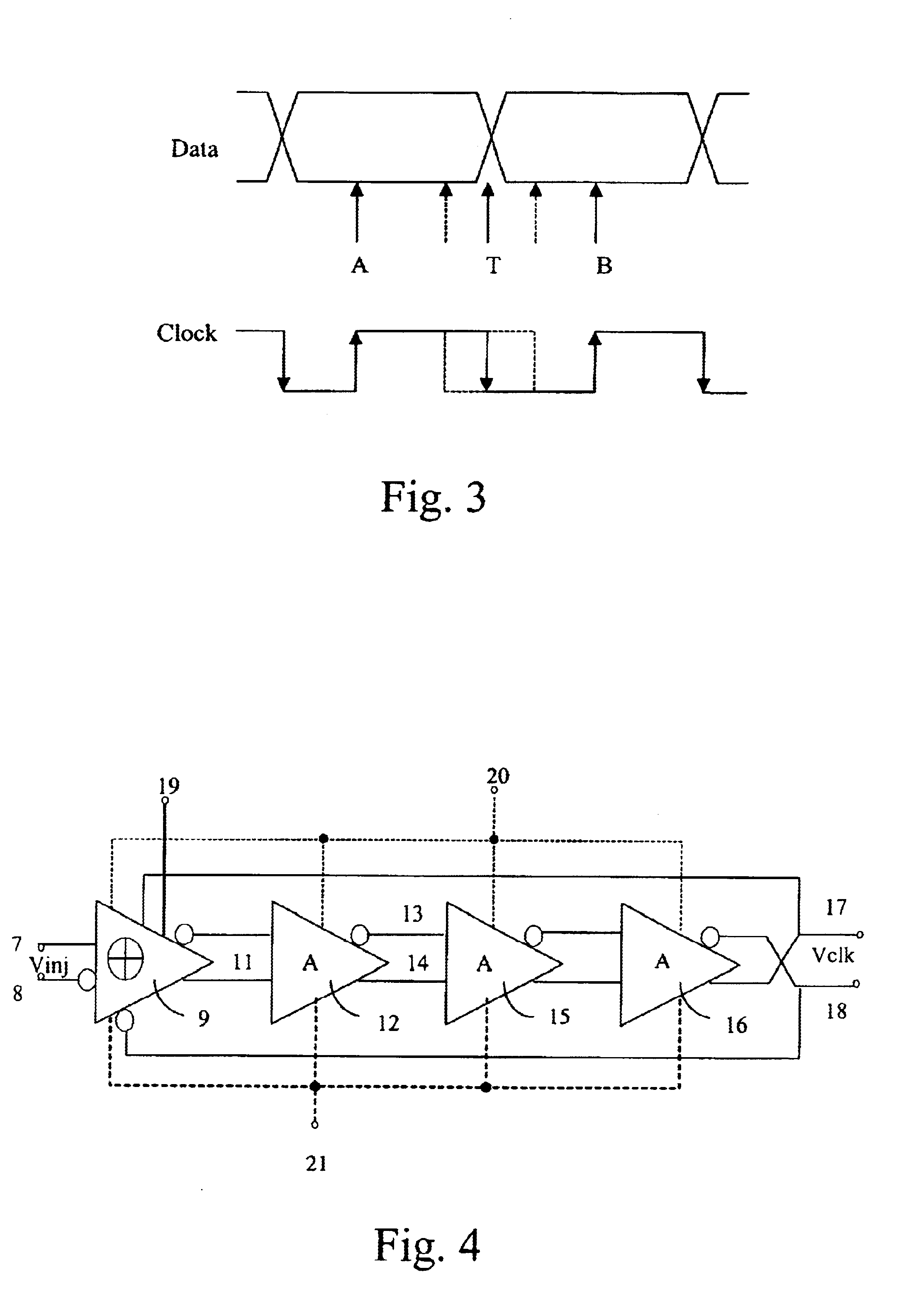
[0033]FIG. 3 shows principle of the digital phase-detector 5 with bang-bang working mode. Data are sampled at the clock rising edge and falling edge. A phase relation of data and clock is decided according to a judgement of the sampled data. Suppose it is def...


PUM


Abstract

The invention discloses an injection synchronization narrowband regenerative phase-locked loop (ISNRPLL) circuit. The circuit includes a synchronous oscillation loop composed by the connecting of an injection synchronization narrowband regenerative voltage-controlled oscillator (ISNRVCO) and an exclusive-OR double frequency circuit; a phase-locked loop composed by the connecting of a digital phase detector, a charge pump and a loop filter, and a D type flip-flop for outputting data. The ISNRVCO does not ask much of the syntonic loop, and can be implemented by integrating inductance on a chip. Preferably, it can be integrated completely by using the deep submicron digital CMOS technology, so there are only a few external elements. Simulation shows that the capture range, capture time and phase noise etc. of the INSRPLL are all better than the conventional phase-locked loop circuit and can be used in GHz level high-speed clock recovery integrated circuit.

Description

FIELD OF THE TECHNOLOGY[0001]The present invention relates generally to a high-speed clock recovery circuit, and more particularly to a circuit design of injection synchronization narrow-band regenerative phase-locked loop (ISNRPLL).BACKGROUND OF THE INVENTION[0002]In high-speed clock recovery integrated circuit design, it is generally applied that passive filter circuit, phase-locked loop (PLL) circuit and synchronous oscillator (SO) circuit. Then, according to the applied different technology and circuit working condition, an appropriate adjustment is taken again.[0003]The advantages of passive filter circuit are simple structure, good frequency phase stability. The disadvantages of passive filter circuit are as follow: it cannot be integrated, working frequency region is narrow, and it cannot be adjusted within a chip.[0004]The advantages of synchronous oscillator circuit are as follow: noise bandwidth without relation with capture range, higher input sensitivity, faster capture ...

Claims


Application Information

Patent Timeline
IPC IPC(8): H03L7/08H03L7/083H04L7/027H04L7/033
CPCH03L7/083H04L7/027H04L7/033
Inventor HUANG, LIZHONG
Owner HUAWEI TECH CO LTD
Learn More