Eureka AIR delivers breakthrough ideas for toughest innovation challenges, trusted by R&D personnel around the world.

Reconfigurable data path processor

a data path processor and reconfigurable technology, applied in the direction of program control, instruments, sustainable buildings, etc., can solve the problems of not optimizing architectures, consuming more and more processing time, and looping programs which require multiple iterations become time-consuming, so as to reduce retracing and re-calculating, reduce the effect of retracing and re-calculating, and eliminate branching

Inactive Publication Date: 2005-04-19
STC UNM +1
View PDF1 Cites 152 Cited by
  • Summary
  • Abstract
  • Description
  • Claims
  • Application Information

AI Technical Summary

Benefits of technology

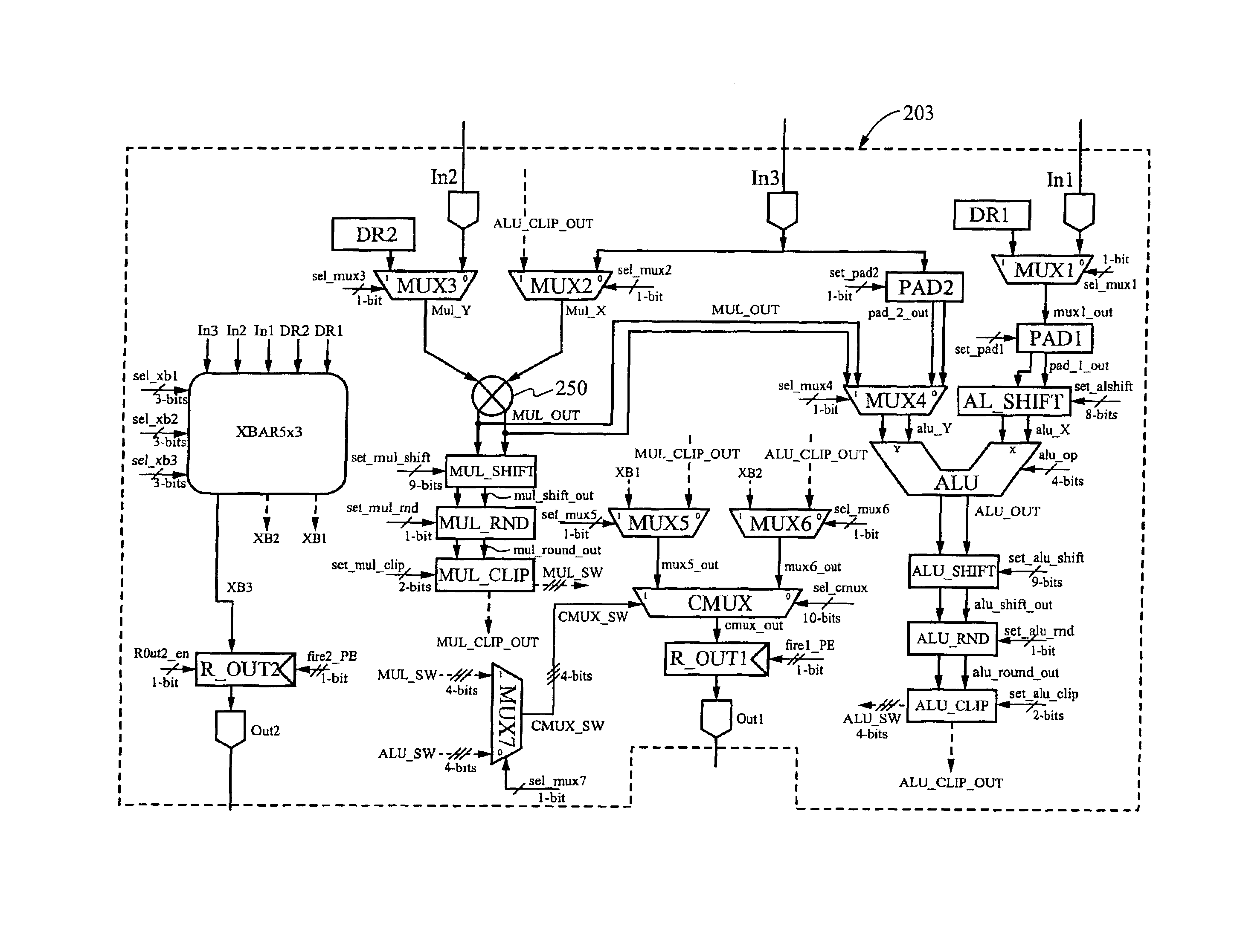
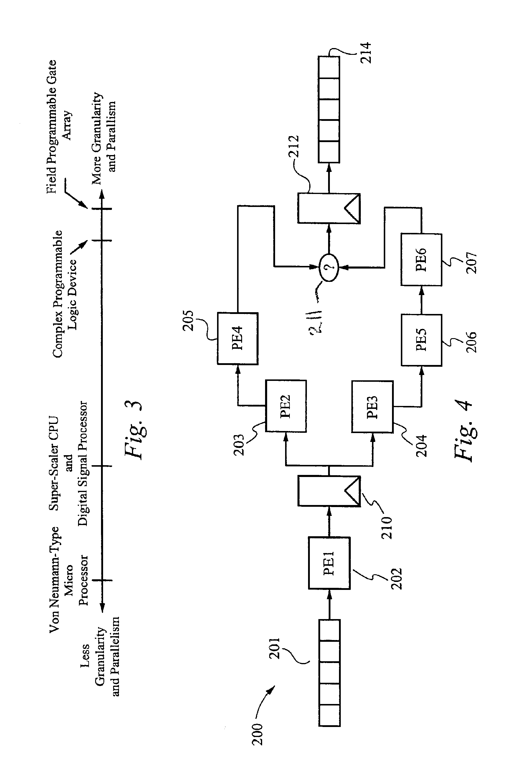
[0011]The present invention eliminates branching, simplifies looping, and reduces retracing and re-calculating by using parallel processing with conditional multiplexers which conditionally switch data paths according to control inputs derived from the data being processed, including the conditional selection of data for processing in parallel data paths. The present invention further provides a processor that can take advantage of the reduction in dynamic power consumption in a ULP circuit through greater parallelism. The present invention further provides a processor which can be easily manufactured to exhibit a high degree of radiation tolerance.

Problems solved by technology

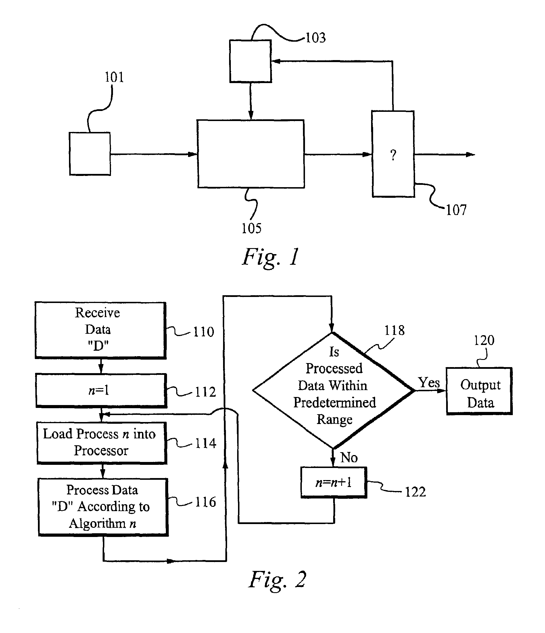
The essential point illustrated by FIG. 2, however, is that looping programs which require multiple iterations become time consuming, each iteration consuming more and more processing time.
Thus, such architectures are not time optimized.
A second limitation of serial processing techniques generally associated with RISC (Reduced Instruction Set Computer), DSP (Digital Signal Processor) and von Neumann type serial processors inheres from the inability of serial processing techniques to take full advantage of ultra low power (“ULP”) technology.
Static, or parasitic power consumption, on the other hand, is generally proportional to the source of the drain area, and therefore increases with the number of transistors in the circuit.
Static power dissipation generally occurs due to leakage in parasitic source and drain diodes.
In conventional CMOS circuits in the 5 volt range, the dynamic power consumption is typically the dominant source of energy consumption.
However, if the same fundamental schematic used in a traditional 5-volt CMOS circuit were used for a ULP circuit, the ratio of power lost through static or parasitic power consumption would increase.
Static power consumption occurs regardless of processing.
However, traditional CMOS processors are not easily radiation hardened without a significant performance degradation.
Without radiation hardening, single event upsets, single event latchup, total ionizing dose and other radiation effects due to cosmic bombardment dramatically increase the likelihood of onboard failure in spacecraft applications.
However, fine-grained reconfigurability exacts a high price in area.
Additionally, FPGAs are not typically radiation-hardened, making them particularly failure-pron in spacecraft applications where cosmic rays are unfiltered by the earth's atmosphere.
Moreover, complex models synthesized from existing gates in FPGAs cannot take advantage of the circuit-level and layout-level optimizations which are attainable when these models are designed by hand.

Method used


Image

  • Reconfigurable data path processor
  • Reconfigurable data path processor
  • Reconfigurable data path processor

Examples


Embodiment Construction

[0032]Reference will now be made in detail to the preferred embodiments of the invention, examples of which are illustrated in the accompanying drawings. While the invention will be described in conjunction with the preferred embodiments, it will be understood that they are not intended to limit the invention to these embodiments. On the contrary, the invention is intended to cover alternatives, modifications and equivalents, which may be included within the spirit and scope of the invention as defined by the appended claims. For example, although the invention described herein is especially useful in space craft applications, the exemplary use of this application herein is not intended to limit the applications of the present invention to space craft applications. Accordingly, many examples and numerous specific details are set forth within the detailed description of this invention in order to provide a thorough understanding of the present invention, and the best mode of its use....


PUM


Abstract

A reconfigurable data path processor comprises a plurality of independent processing elements. Each of the processing elements advantageously comprising an identical architecture. Each processing element comprises a plurality of data processing means for generating a potential output. Each processor is also capable of through-putting an input as a potential output with little or no processing. Each processing element comprises a conditional multiplexer having a first conditional multiplexer input, a second conditional multiplexer input and a conditional multiplexer output. A first potential output value is transmitted to the first conditional multiplexer input, and a second potential output value is transmitted to the second conditional multiplexer output. The conditional multiplexer couples either the first conditional multiplexer input or the second conditional multiplexer input to the conditional multiplexer output, according to an output control command. The output control command is generated by processing a set of arithmetic status-bits through a logical mask. The conditional multiplexer output is coupled to a first processing element output. A first set of arithmetic bits are generated according to the processing of the first processable value. A second set of arithmetic bits may be generated from a second processing operation. The selection of the arithmetic status-bits is performed by an arithmetic-status bit multiplexer selects the desired set of arithmetic status bits from among the first and second set of arithmetic status bits. The conditional multiplexer evaluates the select arithmetic status bits according to logical mask defining an algorithm for evaluating the arithmetic status bits.

Description

RELATED APPLICATIONS[0001]The present application claims priority of the Provisional U.S. Patent Application No. 60 / 307,739 filed on Jul. 25, 2001 and entitled “RECONFIGURABLE DATA PATH PROCESSOR.” The Provisional U.S. Patent Application No. 60 / 307,739 filed on Jul. 25, 2001 and entitled “RECONFIGURABLE DATA PATH PROCESSOR” is herein incorporated by reference.GOVERNMENT LICENSE RIGHTS[0002]The U.S. Government has a paid-up license in this invention and the right in limited circumstances to require the patent owner to license to others on reasonable terms as provided by terms of the Federal Grant No. NAG5-9469 awarded by NASA for the project entitled “RECONFIGURABLE DATA PATH PROCESSOR,” and the Federal Grant No. NAG5-9704 awarded by NASA for the project entitled “SOFTWARE FOR RECONFIGURABLE PROCESSOR.”FIELD OF THE INVENTION[0003]The present invention relates to a reconfigurable data processing pipeline which is adapted to parallel processing in ultra low power CMOS circuitry. More s...

Claims


Application Information

Patent Timeline
Patent Type & Authority Patents(United States)
IPC IPC(8): G06F13/00G06F9/302G06F9/308G06F9/318G06F9/32G06F9/38G06F15/78
CPCG06F9/3001G06F9/30018G06F9/30094G06F9/30101G06F9/30167G06F9/3842G06F9/3885G06F9/3897G06F15/7867G06F9/30181Y02B60/1225Y02B60/1207Y02D10/00
Inventor DONOHOE, GREGORY
Owner STC UNM
Why Eureka
Eureka Blog
Learn More