Ammonia slip catalyst designed to be first in an scr system
a technology of ammonia slip catalyst and scr system, which is applied in the direction of physical/chemical process catalyst, metal/metal-oxide/metal-hydroxide catalyst, separation process, etc., can solve the problems of n2o formation, affecting the health of people, and releasing ammonia excess into the atmosphere, so as to reduce the formation of n2o
- Summary
- Abstract
- Description
- Claims
- Application Information
AI Technical Summary
Benefits of technology
Problems solved by technology
Method used
Image
Examples
example 1
[0091]Catalyst articles were prepared on a cordierite substrate (400 cpsi) by first placing a washcoat comprising a PGM on alumina on the substrate to form a bottom layer, then drying the washcoat. A top layer was placed on the bottom layer by applying a washcoat comprising copper chabazite (Cu-CHA) (120 g / ft3 Cu), then drying the top layer. After the top layer had dried, the article was calcined.
[0092]A reference catalyst article was prepared containing only platinum as the PGM at a loading of 3 g / ft3. A sample comprising Pt and Pd as the PGM was prepared with a total PGM loading of 18 g / ft3, with a Pt:Pd at ratio of 1:5. A sample comprising Pt and Pd as the PGM was prepared with a total PGM loading of 18 g / ft3, with a Pt:Pd at ratio of 2:1.
[0093]The samples were tested fresh and after hydrothermal ageing at 580° C. for 100 hours.
[0094]1″×1″ core of the samples first had N2 gas passed over them as the temperature increased from room temperature to 150° C. Then gas containing NH3=50...
example 2
[0099]Samples of catalysts prepared as describe in Example 1 were placed in an exhaust system along with a diesel oxidation catalyst (DOC) and a catalysed soot filter (CSF). The catalysts were placed in the exhaust system in the order SCR:ASC:DOC:CSF. The exhaust system was connected to engine and urea was injected into the exhaust stream before the SCR catalyst. The outlet from a fuel injector was also located in the system before the SCR. The system was conditioned by running the engine for 1 hour at 450° C., and then the engine speed was reduced to allow the engine temperature to stabilize at about 300° C. After the temperature stabilized, fuel was injected into the exhaust system before the SCR catalyst to raise the temperature after the CSF to about 450° C. After maintaining the temperature after the CSF constant for about 15 minutes, the addition of fuel into the exhaust system was stopped and the temperature was allow to return to about 300° C.
[0100]The temperatures at the in...
example 3
Creation of an Exotherm on the ASC
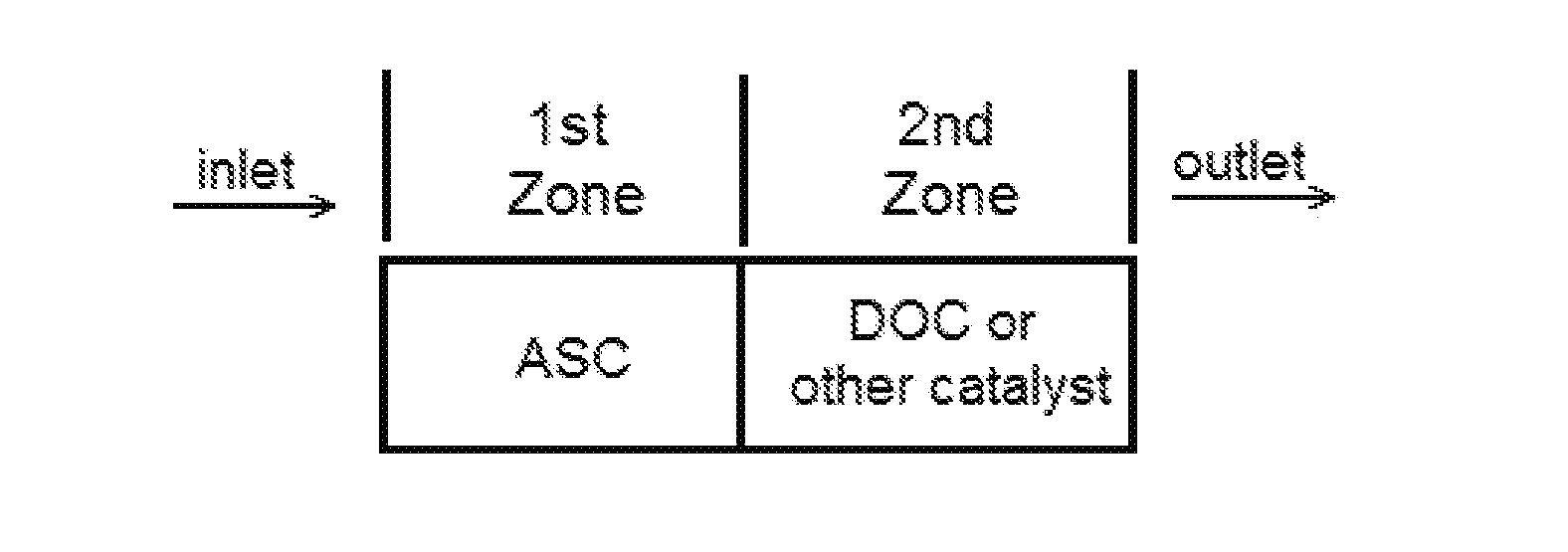
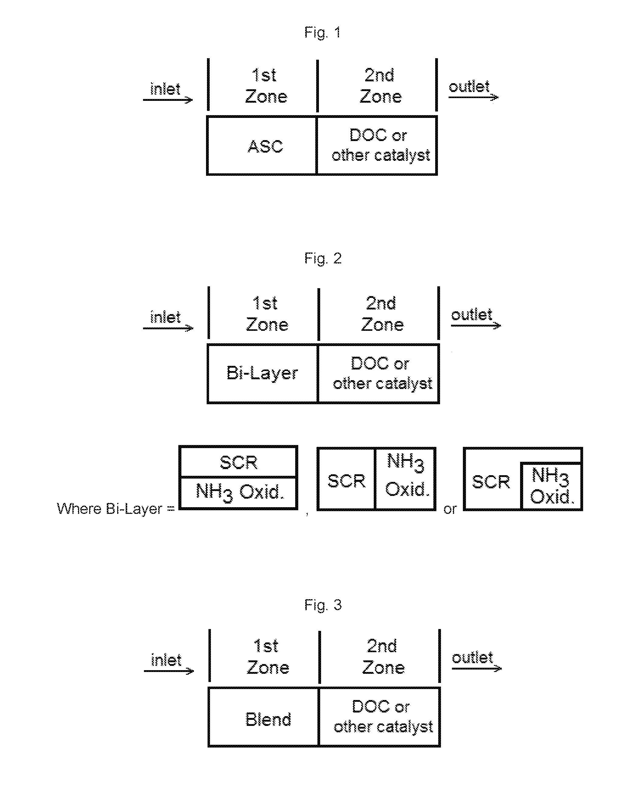
[0103]An ammonia slip catalyst described above is placed first in an exhaust after-treatment system. In a conventional system, an SCR catalyst would be placed in this position, as shown in Example 2. Alternatively, the ammonia slip catalyst is placed in a position such that an exotherm is not be generated upstream of the ammonia slip catalyst.
[0104]The generation of an exotherm can heat the catalyst to a temperature where a catalyst, such as a Cu SCR catalyst, can undergo sulphur regenerated or where the SCR reaction efficiency is increased, leading to better performance in low load operations or in cold starts. When the ASC is first in the system, the generation of an exotherm can allow the catalyst to regenerate itself.
[0105]The presence of a PGM in the catalyst will reduce the risk of highly exothermal reactions in the catalytic system caused by the oxidation of hydrocarbons or other reactive species that can accumulate on a catalyst and be relea...
PUM
| Property | Measurement | Unit |
|---|---|---|
| temperatures | aaaaa | aaaaa |
| temperatures | aaaaa | aaaaa |
| temperatures | aaaaa | aaaaa |
Abstract
Description
Claims
Application Information
 - R&D
- Intellectual Property
- Life Sciences
- Materials
- Tech Scout
- Unparalleled Data Quality
- Higher Quality Content
- 60% Fewer Hallucinations
Browse by: Latest US Patents, China's latest patents, Technical Efficacy Thesaurus, Application Domain, Technology Topic, Popular Technical Reports.
© 2025 PatSnap. All rights reserved.Legal|Privacy policy|Modern Slavery Act Transparency Statement|Sitemap|About US| Contact US: help@patsnap.com


