
High-temperature-resistant metal-packaged fiber bragg grating sensor and manufacturing method therefor

a technology of bragg grating and metal packaging, which is applied in the direction of heat measurement, optical radiation measurement, instruments, etc., to achieve the effects of improving temperature sensitivity and strain sensitivity, good bonding, and reducing the damage to the optical fiber

Active Publication Date: 2015-09-03
EAST CHINA UNIV OF SCI & TECH
View PDF4 Cites 7 Cited by
  • Summary
  • Abstract
  • Description
  • Claims
  • Application Information

AI Technical Summary

Benefits of technology

The present invention provides a high-temperature-resistant metal-packaged fiber Bragg grating sensor that can reliably work under high temperature for a long time and has high temperature sensitivity, strain sensitivity, and strain transfer efficiency. The sensor uses a regenerated fiber Bragg grating obtained via annealing under high temperature as the sensitive element and ensures better bonding between the optical fibers and metals without causing damage to the optical fiber. The sensor is manufactured using a flexible metallic substrate and does not use any organic polymer material during the whole process. The substrate also improves the strain transfer efficiency and is convenient to install.

Problems solved by technology

1) Reflectivity of conventional fiber Bragg gratings start to decay when the temperature is above 200° C. and the gratings are “erased” completely when up to 680° C. So conventional fiber Bragg grating sensors can only be used below 200° C.
2) During fabrication of gratings, polymer coatings on surfaces of the optical fibers are always removed so that the optical fibers are exposed to moisture and easily to be mechanically damaged resulting in crack formation on the surfaces, which causes the strength of optical fiber decreases. So the optical fibers must be recoated and packaged after inscribing gratings. Normally, it is mainly organic polymer materials which are used to recoat and packaged fiber Bragg gratings, for example, Chinese patent application No. 201110135194.2 discloses a metal-packaged fiber grating sensor and manufacturing method thereof. The disadvantages of polymer materials, such as ageing and creep, restrict the performance of sensors thus hard to survive in the damp and hot environment. When it is above their normal work temperature, the polymer materials will soften and even decompose to generate hydrogen gas which has a stress corrosion effect on silica optical fibers thereby accelerate fatigue of the silica optical fibers. When it is above 400° C., the polymer materials decompose completely so that optical fibers lose their protection in harsh environment and easily form cracks on their surfaces under thermal-mechanical loading. As time goes by, the cracks grow slowly which results in a decrease in the strength and eventually causes fracture of the optical fiber. Apparently, it is hard to monitor high-temperature components for a long time based on conventional fiber Bragg grating sensors.
3) Conventional fiber Bragg grating sensors and components to be monitored are usually connected by organic adhesive. While, the organic adhesive will produce measurement redundancy, lower strain transfer efficiency, poor linearity, poor repeatability and poor long-term reliability. With increasing in temperature, the organic adhesive accelerates its ageing and further starts to soften and even decompose when up to more than 250° C. Thus the connection between the sensors and the high-temperature components could hardly be achieved.
4) Low thermo-optic coefficient and thermal expansion coefficient of silica (SiO2) optical fiber result in the low temperature sensitivity of bare fiber Bragg grating sensors.
However, the specially doped optical fibers are expensive, etching gratings on surfaces requires high accuracy and the corresponding packaging is very difficult since the grating is etched on the cladding and the femtosecond laser costs too much.
Casting and laser cladding have a lot of restriction on coated metals, wherein metals with low melting points cannot meet the requirement of high temperature application; and metals with high melting points have too high melting temperature under which optical fiber gratings are easily damaged and would cause high thermal stress leading to fracture of optical fibers.
Furthermore, both of the two methods cannot ensure a metallic coating uniformly deposited on the surface of a grating along an axial direction thereof so that polarization phenomenon occurs and influences spectral shape.
The bonding between the coatings obtained from electroless plating and the optical fibers is poor and the coatings have poor uniformity, which cannot meet the requirements of high sensitivity sensors.
Moreover, the coarsening and sensitizing process during pretreatment of the electroless plating will damage surfaces of the optical fibers and reduce strength of the optical fibers.
A bonding force between coating and a substrate surface is weak during vacuum evaporation, and it is difficult to deposit a coating with a high melting point under low vapor pressure, and crucible materials for evaporating substance will evaporate and become impurities mixed into the coating.
Also, the coating obtained from vacuum evaporation is too thin to sufficiently protect the optical fibers and transfer strain from the measured components to optical fibers.

Method used


Image

  • High-temperature-resistant metal-packaged fiber bragg grating sensor and manufacturing method therefor
  • High-temperature-resistant metal-packaged fiber bragg grating sensor and manufacturing method therefor
  • High-temperature-resistant metal-packaged fiber bragg grating sensor and manufacturing method therefor

Examples


Embodiment Construction

[0036]The advantages of the invention are illustrated in detail by referring the accompanying drawings and embodiments.

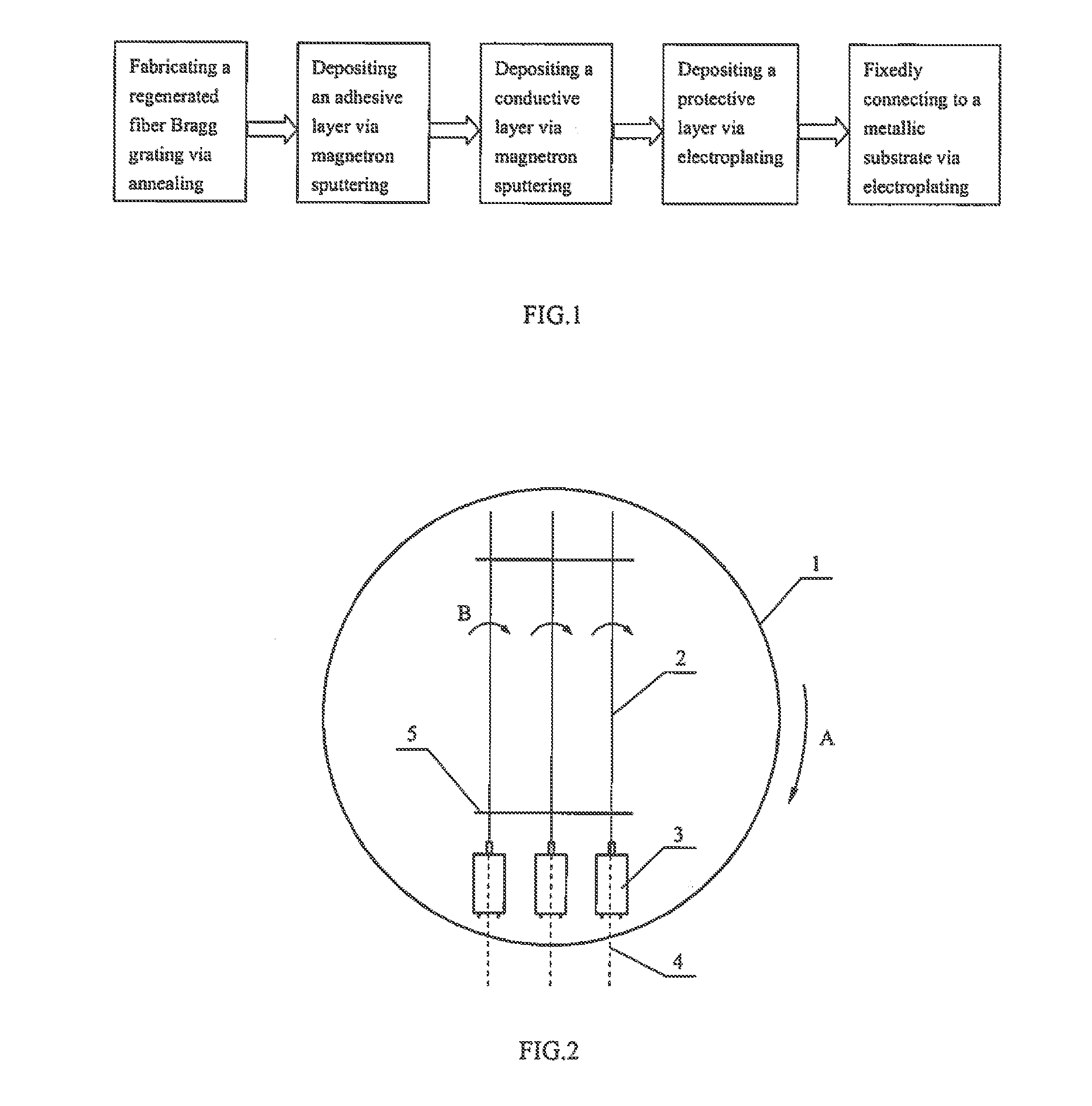
[0037]FIG. 1 shows a flowchart of manufacturing a high-temperature-resistant metal-packaged fiber Bragg grating sensor according to the present invention, wherein the steps include:

[0038]1) Obtaining a regenerated fiber Bragg grating via annealing treatment on a fiber Bragg grating.

[0039]In order to avoid grating being “erased” at high temperature, a commercial fiber Bragg grating needs to be annealed to fabricate a high-temperature-resistant regenerated fiber Bragg grating, which specific process parameters are shown in Table 1.

TABLE 1Annealing temperature (° C.)Annealing time (min)850-100030-120

[0040]After the annealing, the regenerated fiber Bragg grating can withstand temperature up to 1000° C., and organic material coatings in and around the grating area have been removed completely.

[0041]2) Depositing an adhesive layer by magnetron sputtering, a conductive lay...


PUM

PropertyMeasurementUnit
temperatureaaaaaaaaaa
concentrationaaaaaaaaaa

Abstract

A manufacturing method for a high-temperature-resistant metal-packaged fiber Bragg grating sensor includes using a regenerated fiber Bragg grating obtained via high-temperature annealing as a sensitive element so that the grating will not be erased when used at high temperature. The method also includes using a magnetron sputtering method which makes an optical fiber and metal combine better to form on the surface of the optical fiber an adhesive layer and a conductive layer, thereby causing little damage to optical fiber because of the absence of the processes of coarsening, sensitization, etc. of electroless plating and the fact that the method is performed in an anhydrous environment. After magnetron sputtering, the method includes using an electroplating method to thicken and deposit a protective layer, and embedding the optical fiber in a flexible-structure metallic substrate through the electroplating method to achieve the all-metal package.

Description

BACKGROUND OF THE INVENTION[0001]1. Field of the Invention[0002]The present invention is related to a high-temperature-resistant metal-packaged fiber Bragg grating sensor and manufacturing method thereof.[0003]2. Description of Related Art[0004]Optical fiber sensors are used for detecting changes in light transmission characteristics when light propagates through optical fibers being modulated by the environmental effects (physical parameters, chemical parameters, biological parameters, etc.) where all or parts of the optical fibers are located. Optical fiber sensors are widely used in various industries due to their many advantages, such as small size, light weight, high accuracy and sensitivity, immunity to electromagnetic interference and radiation, corrosion resistance, fire prevention, explosion proof, and long service life.[0005]Fiber grating sensor based on wavelength modulation is a type of optical fiber sensors. A fiber grating sensor is to monitor a shift in wavelength whi...

Claims


Application Information

Patent Timeline
Patent Type & Authority Applications(United States)
IPC IPC(8): G01D5/353C25D3/04C25D7/00C25D3/12C23C14/35C23C14/16G01K11/3206
CPCG01D5/353C23C14/35C25D3/04C25D7/00C25D3/12C23C14/165G02B6/0218G02B6/02185G02B6/02209G01D5/35316C23C14/185C23C14/025
Inventor TU, SHANDONGTU, YUNQI, YIHUAHAN, PENGZHANG, XIANCHENGXUAN, FUZHEN
Owner EAST CHINA UNIV OF SCI & TECH
Learn More