Eureka AIR delivers breakthrough ideas for toughest innovation challenges, trusted by R&D personnel around the world.

Method of operating a lithium-ion cell having a high-capacity cathode

a lithium-ion battery and cathode technology, applied in the field of lithium-ion batteries, can solve the problems of low energy density of lithium-ion cells, limited practical specific capacity achievable with current cathode materials, and inability to obtain corresponding high-capacity cathode materials, etc., to achieve fast discharging of cells, reduce solid-state diffusion time, and high power density

Active Publication Date: 2013-10-17
GLOBAL GRAPHENE GRP INC
View PDF10 Cites 96 Cited by
  • Summary
  • Abstract
  • Description
  • Claims
  • Application Information

AI Technical Summary

Benefits of technology

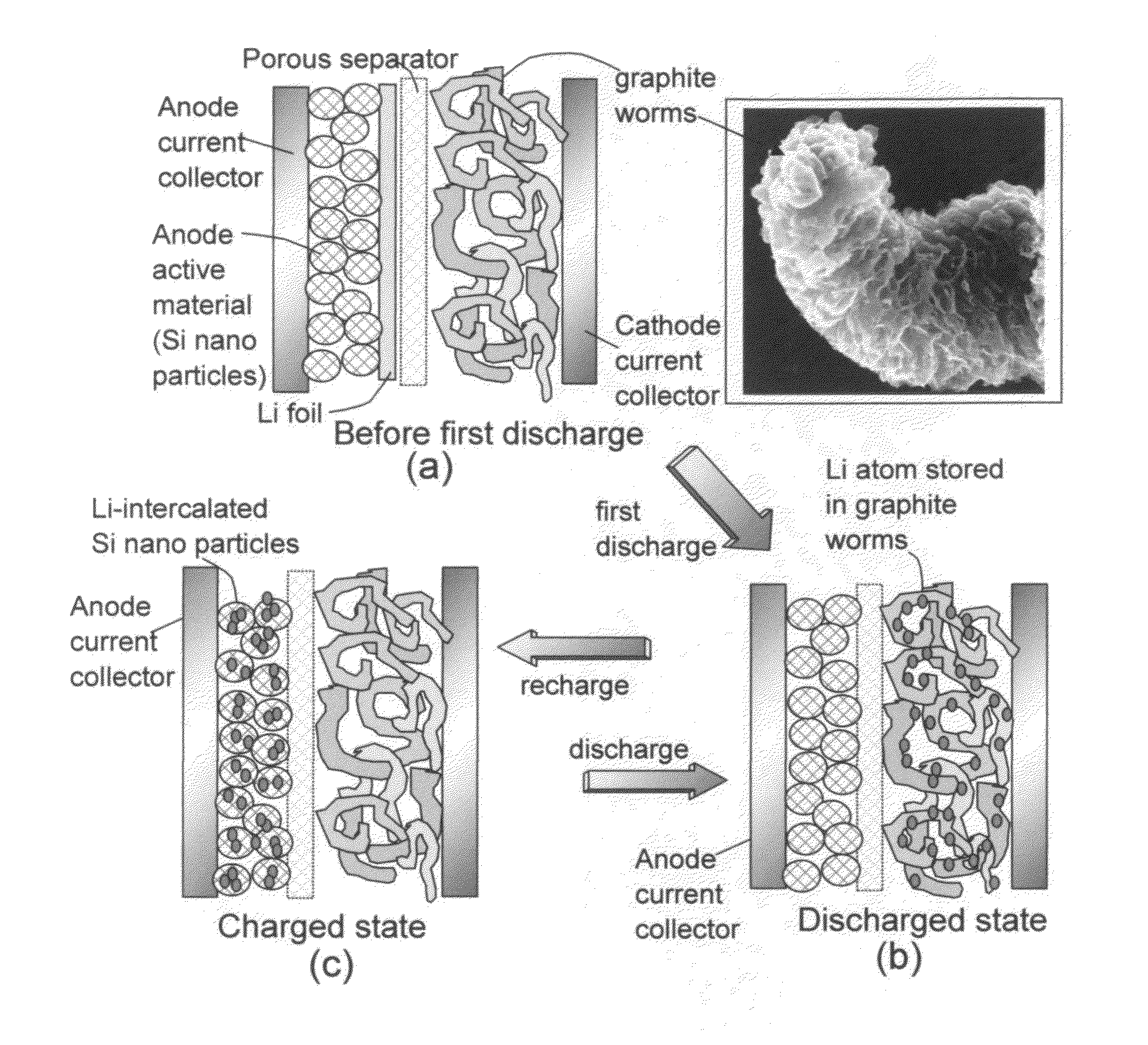
The patent describes a new type of battery that uses a special liquid electrolyte or gel electrolyte containing lithium ions. The electrolyte is preferably an organic liquid or ionic liquid, and the battery has a high power density and can be quickly discharged. The anode active material is made into a nano-structure to increase the surface area in contact with the electrolyte and allow for faster solid-state diffusion of lithium ions. The cathode active material has a high specific surface area that can capture lithium ions from the electrolyte and store them in the surface active sites. This new technology is faster, safer, and has higher energy density than traditional batteries.

Problems solved by technology

For over three decades, battery scientists have been frustrated with the low energy density of lithium-ion cells primarily due to the low lithium-storing capacity of all existing cathode active materials.
Specifically, the practical specific capacity achievable with current cathode materials has been limited to the range of 150-250 mAh / g, mostly less than 200 mAh / g.
Although several high-capacity anode active materials have been found (e.g., Si with a theoretical capacity of 4,200 mAh / g), there has been no corresponding high-capacity cathode material available.
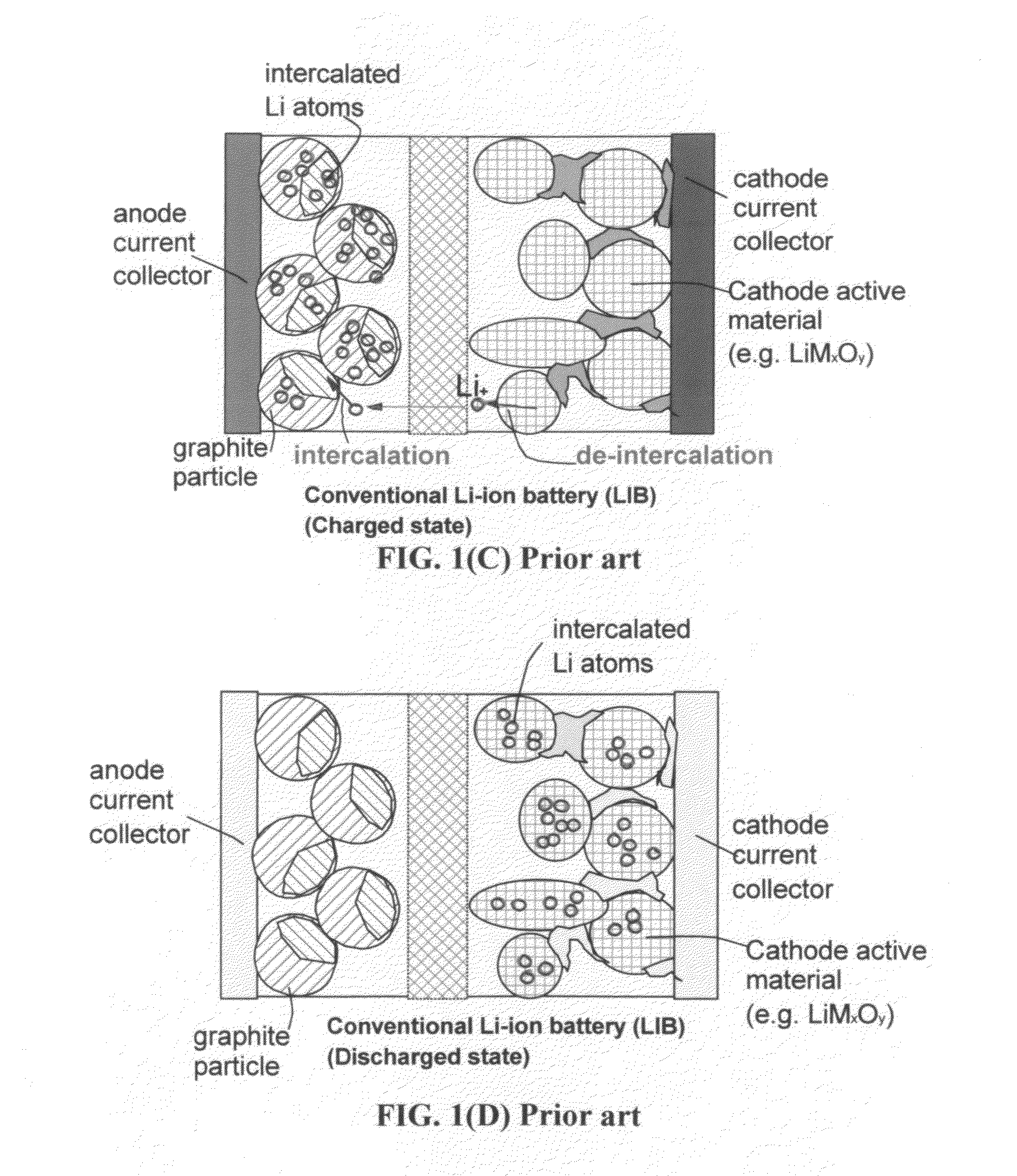
Further, most of the commercially available Li-ion cells make use of carbon- or graphite-based anodes, which have several significant drawbacks: low specific capacity (theoretical capacity of only 372 mAh / g of graphite), slow Li intercalation (due to low solid-state diffusion coefficients of Li in graphite) resulting in a long recharge time, inability to deliver high pulse power, and necessity to use lithiated cathodes (e.g. lithium cobalt oxide), thereby limiting the choice of available cathode materials.
Furthermore, these commonly used cathodes also rely upon extremely slow Li diffusion in the solid state.
First, the commonly used cathode materials, such as lithium cobalt oxide and lithium iron phosphate, have relatively low specific capacities and, hence, a strong need exists for a higher-capacity cathode.
Second, it is commonly understood in the battery industry and the field of electrochemistry that if a material is a good anode active material for a lithium-ion cell, the same material is usually not considered to be a viable cathode active material for a lithium-ion cell from the electrochemical potential perspective.
1(F)), thus requiring a long re-charge time as well.
During discharge, lithium ions must also diffuse out of the interior of graphite particles, thereby compromising the power density.
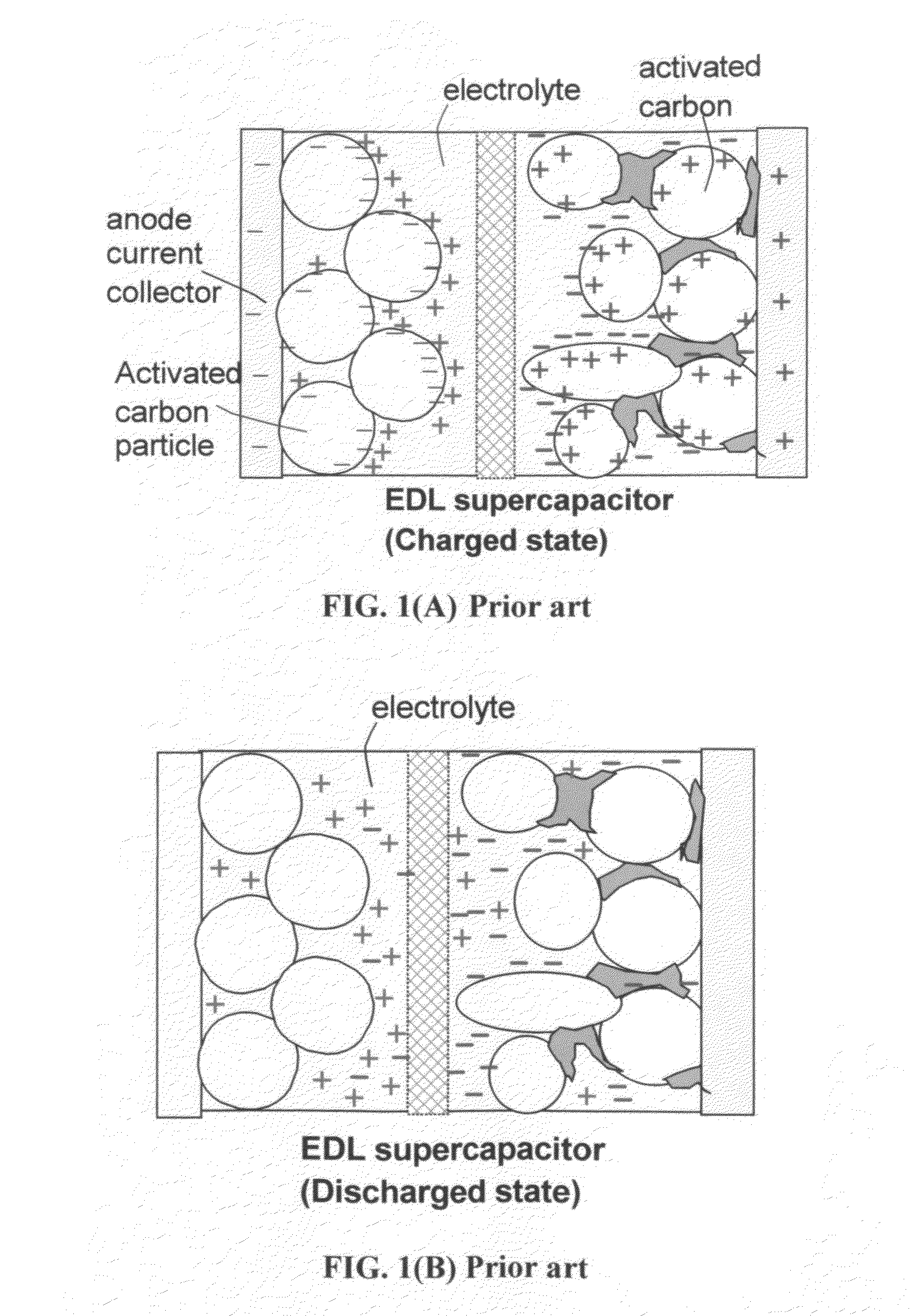
Hence, this is a totally new class of energy storage device that exhibits unparalleled and unprecedented combined performance of an exceptional power density, high energy density, long and stable cycle life, and wide operating temperature range.
(1) The practical capacity achievable with current cathode materials (e.g. lithium iron phosphate and lithium transition metal oxides) has been limited to the range of 150-250 mAh / g and, in most cases, less than 200 mAh / g.
(2) The production of these cathode active materials normally has to go through a high-temperature sintering procedure for a long duration of time, a tedious, energy-intensive, and difficult-to-control process.
(3) The insertion and extraction of lithium in and out of these commonly used cathodes rely upon extremely slow solid-state diffusion of Li in solid particles having very low diffusion coefficients (typically 10−8 to 10−14 cm2 / s), leading to a very low power density (another long-standing problem of today's lithium-ion batteries).
(4) The current cathode materials are electrically and thermally insulating, not capable of effectively and efficiently transporting electrons and heat. The low electrical conductivity means high internal resistance and the necessity to add a large amount of conductive additives, effectively reducing the proportion of electrochemically active material in the cathode that already has a low capacity. The low thermal conductivity also implies a higher tendency to undergo thermal runaway, a major safety issue in lithium battery industry.
(5) The most commonly used cathodes, including lithium transition metal oxides and lithium iron phosphate, contain a high oxygen content that could assist in accelerating the thermal runaway and provide oxygen for electrolyte oxidation, increasing the danger of explosion or fire hazard This is a serious problem that has hampered the widespread implementation of electric vehicles.

Method used


Image

  • Method of operating a lithium-ion cell having a high-capacity cathode
  • Method of operating a lithium-ion cell having a high-capacity cathode
  • Method of operating a lithium-ion cell having a high-capacity cathode

Examples


example 1

Meso-Porous Soft Carbon

[0132]Chemically etched or expanded soft carbon was prepared from a liquid crystalline aromatic resin. The resin was ground with a mortar, and calcined at 900° C. for 2 h in a N2 atmosphere to prepare the graphitizable carbon or soft carbon. The resulting soft carbon was mixed with small tablets of KOH (four-fold weight) in an alumina melting pot. Subsequently, the soft carbon containing KOH was heated at 750° C. for 2 h in N2. Upon cooling, the alkali-rich residual carbon was washed with hot water until the outlet water reached a pH value of 7. The resulting chemically etched or expanded soft carbon was dried by heating at 60° C. in a vacuum for 24 hours.

example 2

Expanded Activated Carbon (E-AC)

[0133]Activated carbon (AC, from Ashbury Carbon Co.) was treated with an acid solution (sulfuric acid, nitric acid, and potassium permanganate at a ratio of 4:1:0.05) for 24 hours. Upon completion of the reaction, the mixture was poured into deionized water and filtered. The treated AC was repeatedly washed in a 5% solution of HCl to remove most of the sulphate ions. The sample was then washed repeatedly with deionized water until the pH of the filtrate was neutral. The slurry was then dried in a vacuum oven pre-set at 70° C. for 24 hours. The dried sample was then placed in a tube furnace at 1,050° C. for 2 minutes to obtain expanded AC.

example 3

Chemically Treated Needle Coke

[0134]Anisotropic needle coke has a fully developed needle-shape texture of optical anisotropy. Volatile species of the raw coke was estimated to be around 5 wt. %. Activation was carried out using KOH in a reaction apparatus that consisted of a stainless steel tube and a nickel sample holder. KOH activation was carried out at 800° C. for 2 h under Ar flow. The coke / KOH ratio was varied between 1 / 1 and 1 / 4. Upon cooling, the alkali-rich coke was washed with hot water until the outlet water reached a pH value of 7. The resulting chemically etched or expanded coke was dried by heating at 60° C. in a vacuum for 24 hours.


PUM

PropertyMeasurementUnit
specific surface areaaaaaaaaaaa
pore sizeaaaaaaaaaa
open circuit voltageaaaaaaaaaa

Abstract

A method of operating a lithium-ion cell comprising (a) a cathode comprising a carbon or graphitic material having a surface area to capture and store lithium thereon; (b) an anode comprising an anode active material; (c) a porous separator disposed between the two electrodes; (d) an electrolyte in ionic contact with the two electrodes; and (e) a lithium source disposed in at least one of the two electrodes to obtain an open circuit voltage (OCV) from 0.5 volts to 2.8 volts when the cell is made; wherein the method comprises: (A) electrochemically forming the cell from the OCV to either a first lower voltage limit (LVL) or a first upper voltage limit (UVL), wherein the first LVL is no lower than 0.1 volts and the first UVL is no higher than 4.6 volts; and (B) cycling the cell between a second LVL and a second UVL.

Description

[0001]The present invention is based on the research results of a project sponsored by the US DOE Vehicle Technology Program.[0002]This application claims the benefits of the following co-pending applications: (1) Guorong Chen, Yanbo Wang, Qing Fang, Xiqing Wang, Aruna Zhamu, and Bor Z. Jang, “Lithium-ion Cell Having a High-Capacity Anode and a High-Capacity Cathode,” U.S. patent application Ser. No. 13 / 385,561 (Feb. 27, 2012); (2) Guorong Chen, Yanbo Wang, Qing Fang, Xiqing Wang, Aruna Zhamu, and Bor Z. Jang, “Lithium-ion Cell Having a High Energy Density and High Power Density” US patent application Submitted on Apr. 1, 2012.FIELD OF THE INVENTION[0003]This invention relates generally to the field of lithium-ion battery and, more particularly, to a lithium-ion cell having a high-capacity anode and a meso-porous graphitic material-based high-capacity cathode.BACKGROUND OF THE INVENTION[0004]For over three decades, battery scientists have been frustrated with the low energy density ...

Claims


Application Information

Patent Timeline
Patent Type & Authority Applications(United States)
IPC IPC(8): H02J7/00H01M10/02B82Y30/00B82Y99/00
CPCB82Y30/00H01G11/50H01M4/0445H01M4/133H01M4/1393H01M4/38H01M4/386H01M4/387H01M4/483H01M4/587H01M10/0525H01M10/44H01M2004/028Y02E60/10Y02T10/70Y02E60/13
Inventor CHEN, GUORONGZHAMU, ARUNAWANG, XIGINGJANG, BOR Z.WANG, YANBOFANG, QING
Owner GLOBAL GRAPHENE GRP INC
Why Eureka
Eureka Blog
Learn More