
Battery separator comprising a polyolefin nanofilament porous sheet

a polyolefin nanofilament and separator technology, applied in the field of battery separator comprising a porous sheet, can solve the problems of insufficient fineness of filament obtained in this manner, complicated process, and limitation of film method, and achieve low internal resistance, good conductivity, and high porosity ratio

Active Publication Date: 2013-03-14
UNIVERSITY OF YAMANASHI
View PDF4 Cites 8 Cited by
  • Summary
  • Abstract
  • Description
  • Claims
  • Application Information

AI Technical Summary

Benefits of technology

The present invention is a new battery separator made of nanofilaments that has high porosity and low internal resistance, allowing good conductivity. It also prevents damage to the electrodes and prevents short circuits, making it suitable for secondary lithium batteries. The separator is made of polyolefin filaments, which are chemically stable and resistant to decomposition. The filaments are highly drawn, resulting in enhanced strength and handling ability when used in batteries. The porous sheet used as a battery separator has uniform pore size and high performance. The method used to produce the nanofibers is simple and cost-effective, resulting in consistent and productive manufacturing.

Problems solved by technology

A porous film comprising a polyolefin film has previously been used as a battery separator, but the film method had a limitation of increasing the number of pores.
However, the use of a sea-islands structure type fiber method to manufacture a fine filament made the process complicated.
The filament obtained in this manner was not sufficiently fine, and the steps needed to cut the filament and convert the short fibers into a non-woven cloth were complex, creating problems in terms of both quality and cost.
However, the ES method, which involves dissolving a polymer in a solvent and applying high voltage, is unacceptable in the case that there is no safe solvent, such as in the case of polyolefin.
In addition, a web created using the ES method does not contain continuous filaments and also contains short fibers since the filaments are cut during spinning.
One of the problems is the generation of many molten resin lumps that are larger than the fiber diameter due to the shrinkage of cut sections during spinning.
In addition, many defects greater than the fiber diameter were thought to be generated, resulting in problems similar to those observed in the solvent method.
Furthermore, both a laser and a high voltage electrode were used in the manufacturing process which results in a complex process and causes both quality and cost problems when the process is used to manufacture a battery separator.
Moreover, a melt-blown method is also one of the manufacturing processes used to create a super fine filament non-woven cloth, but the filament diameter reaches a nanoscale only with difficulty and the generation of molten resin lumps causes similar problems.

Method used

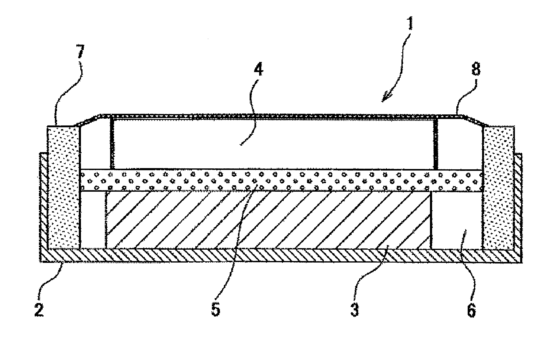
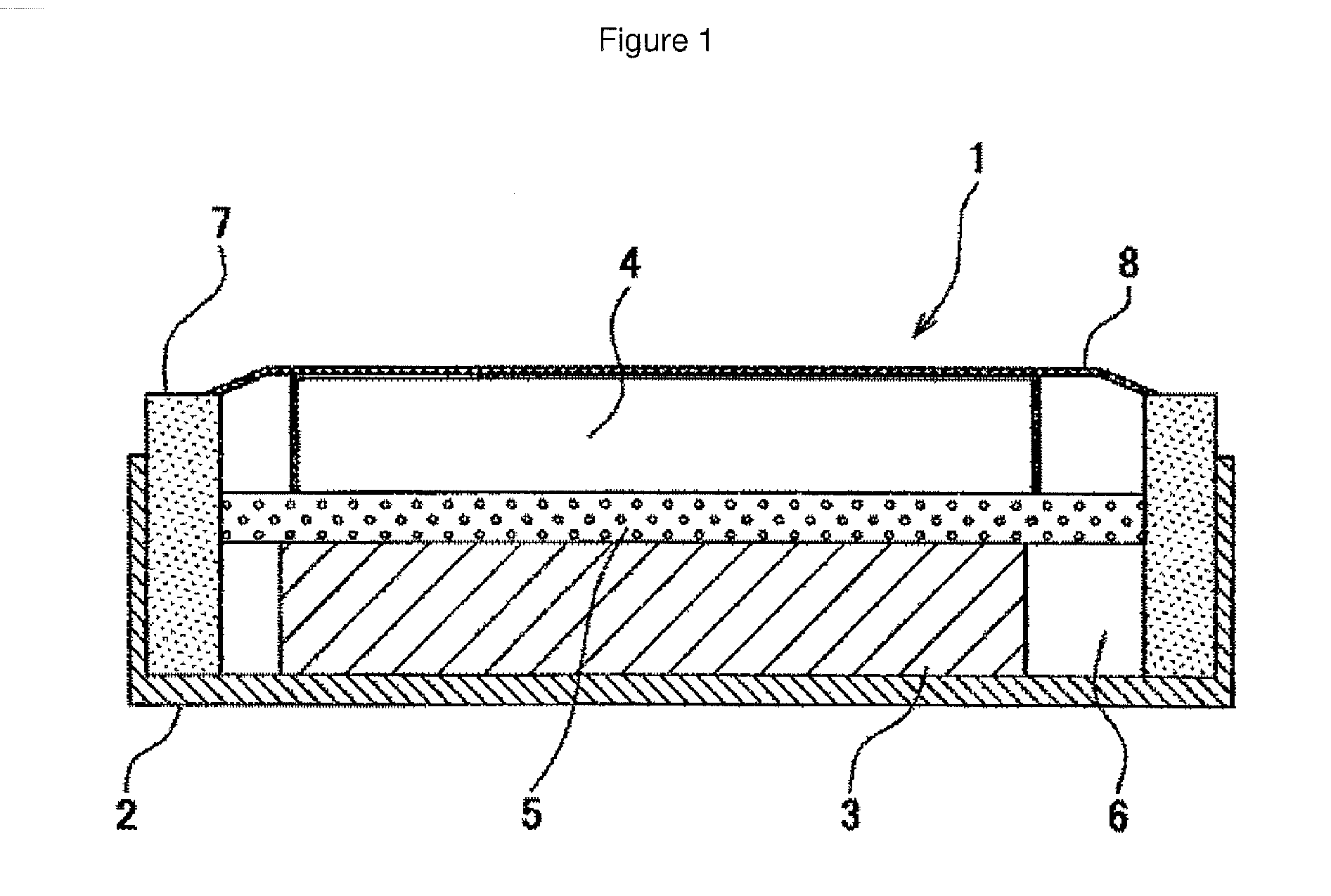
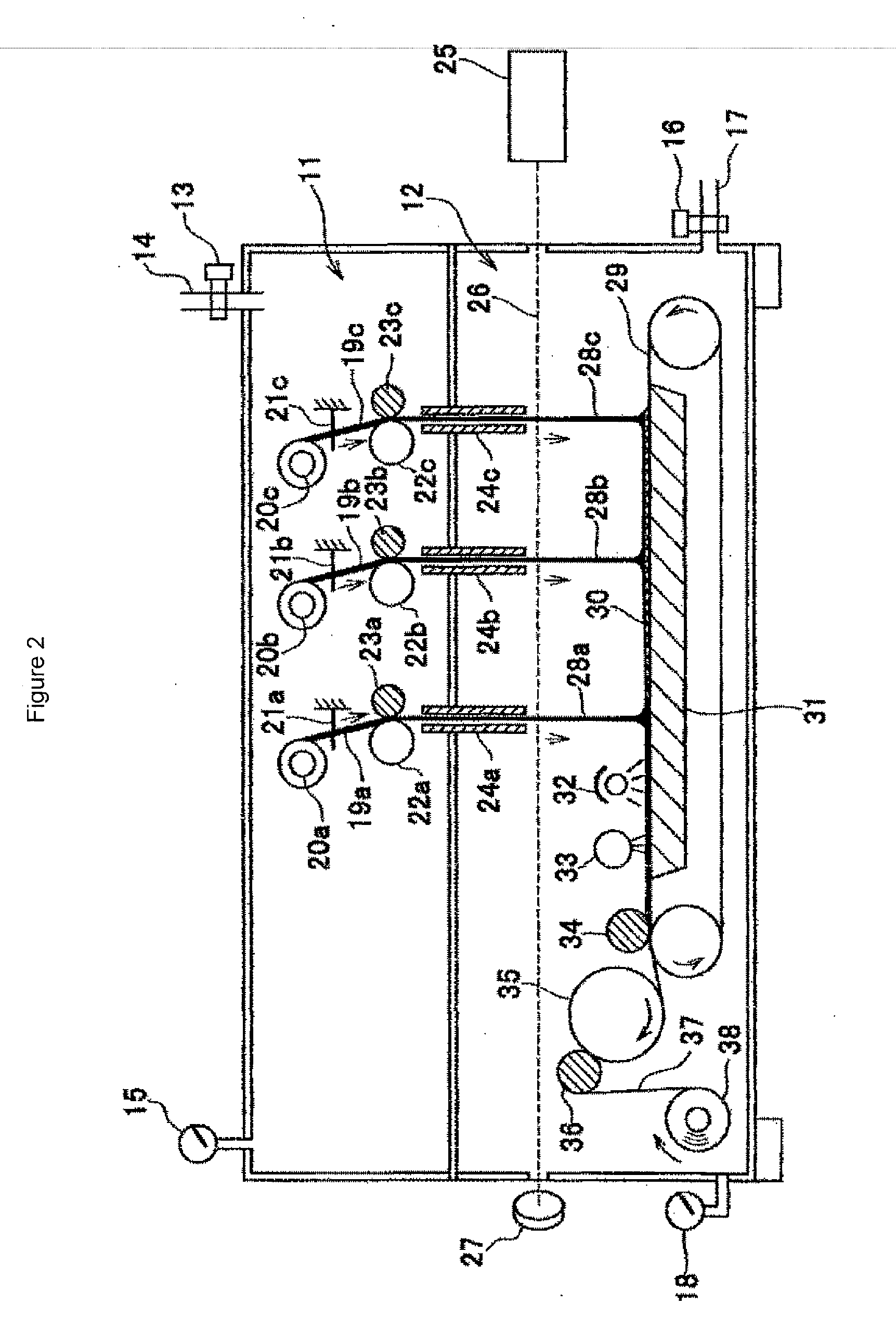

Image

  • Battery separator comprising a polyolefin nanofilament porous sheet
  • Battery separator comprising a polyolefin nanofilament porous sheet
  • Battery separator comprising a polyolefin nanofilament porous sheet

Examples


example 1

[0061]163.2 μm polypropylene filaments were prepared as original filaments. The weight average molecular weight of the polymer was 349,000, and the number average molecular weight was 89,300. The isotacticity was 92.4%. In the equipment shown in FIG. 3, the laser beam diameter of the laser generated by the carbon dioxide gas laser emitting device was 3.5 mm. The experiment was conducted using an internal orifice diameter of 0.3 mm, seven orifices and filament supply rate of 0.1 m / min. The drawing ratios calculated using the filament diameter when the laser power was changed from 10 W to 25 W at a degree of vacuum in the drawing chamber of 10 kPa are shown in Table 2. According to the data in Table 2, the average filament diameter was already in the nanofilament zone when the laser power was 10 W, and the standard deviation for the filament diameter distribution was as low as 0.12. Thus the calculated drawing ratio exceeded 200,000. The standard deviation further decreased to 0.0455 ...

example 2

[0062]Differential scanning calorimetry (DSC) measurements were conducted on the filaments obtained in Example 1, described above, and the results are shown in Table 3 and FIG. 8. The FIG. 8 showed that the endothermic peak was suddenly sharpened upon drawing, indicating increase in crystallinity. The table 3 also showed increase in melting point, the heat of fusion (ΔHm) and the crystallinity indices (Xc) as average filament diameter (day) decreased. These results suggested the enhanced molecular orientation in the filaments.

TABLE 3TmΔHmXcdavSample(° C.)(J / g)(%)(nm)Original159.9−95.8445.9163.2FilamentPower 10 W158.7 / 163.1−104.0749.80.364Power 15 W161.6−106.0850.80.339Power 20 W160.7−110.6452.90.220Power 25 W160.0−108.851.10.188Filament supply rate: 0.1 m / minP2: 10 kPa

example 3

[0063]The equipment in Example 1 was used with the same original filaments. The filaments were directly wound for ten minutes on a winding tube in the lower section (FIG. 3) using a drawing chamber with a degree of vacuum of 20 kPa, filament supply rate of 0.1 m / min and laser power of 20 W. The wound sheet was cut from the winding tube to obtain porous sheets 18 cm wide, 17 cm long, with a weight of 4.16 g / m2 and average filament diameter of 0.409 μm. A single layer laminated cell with a battery separator obtained using this sheet was prepared (FIG. 9), and various properties of the battery were measured. The results are shown in Tables 4 and 5. Now, the comparative example was a monoaxially drawn porous polypropylene film (trade name “CELGARD,” 25 μm thick). The positive electrode of the battery was a molded product containing 89 wt % LiCoO2, 6 wt % conductive carbon black and 5 wt % binder [poly(vinylidene fluoride)]. The negative electrode was molded using 90 wt % mesocarbon grap...


PUM

PropertyMeasurementUnit
diameteraaaaaaaaaa
temperatureaaaaaaaaaa
melting pointaaaaaaaaaa

Abstract

Disclosed is a highly safe battery separator, in particular a separator for a lithium ion secondary battery, which reduces internal resistance, achieves good ionic conductivity, prevents passing of electrode active materials, and also prevents electrical short circuit by controlling deposition of lithium metal (dendrite). Also disclosed is a means for stably producing the battery separator with high productivity. Specifically disclosed are: a battery separator which is composed of a porous polyolefin sheet that is formed from a group of polyolefin nanofilaments that have an average filament diameter of less than 1 μm and a filament size distribution of 0.2 or less; and a means for producing the battery separator.

Description

FIELD OF THE INVENTION[0001]The present invention relates to a battery separator comprising a porous sheet composed of polyolefin filaments whose average diameter is less than 1 μm, and relates more specifically to a highly safe lithium-ion secondary battery which has low internal resistance and good ionic conductivity, prevents passing of electrode active material, and also prevents electrical short circuit by controlling lithium metal depositions (dendrites).BACKGROUND OF THE INVENTION[0002]Evolutionary improvement of batteries is the most important element in recent advancements of electric automobiles and mobile electrical devices. A battery separator is a basic structural element of a battery, and improving performance of the separator is an important factor in achieving higher battery performance and making batteries smaller and safer. A porous film comprising a polyolefin film has previously been used as a battery separator, but the film method had a limitation of increasing ...

Claims


Application Information

Patent Timeline
Patent Type & Authority Applications(United States)
IPC IPC(8): H01M2/16D04H3/016D04H3/03H01M50/403H01M50/417
CPCD04H3/016H01M2/162Y10T29/49108D04H3/03H01M2/145H01M10/0525Y02E60/10H01M50/44H01M50/417D04H3/007D04H3/02D02J1/22H01M50/491B82Y40/00D10B2401/10D10B2505/00
Inventor SUZUKI, AKIHIROTOYOOKA, TAKEHIROMATSUO, AKIRANISHIZAWA, TAKESHIOMARU, ATSUO
Owner UNIVERSITY OF YAMANASHI
Learn More