
Composite nanowire compositions and methods of synthesis

Inactive Publication Date: 2012-04-19
UT BATTELLE LLC
View PDF4 Cites 64 Cited by
  • Summary
  • Abstract
  • Description
  • Claims
  • Application Information

AI Technical Summary

Benefits of technology

[0008]In a first embodiment, the invention is directed to an array of nanowires, wherein the nanowires contain a transition metal core surrounded by a shell containing at least one Group IV metal selected from silicon, germanium, and tin, herein also referred to as “(transition metal core)-(Group IV metal shell) nanowires”. Preferably, the array of nanowires possesses a significant degree of spatial ordering and / or uniformity in alignment and / or thickness. The nanowires in the array are also preferably not in contact with each other. The shell generally provides high capacity while the core functions as the built-in current collector and provides mechanical support and toughness. The core-shell nanowire structure allows very short (nm) transport paths for both the Li-ions and electrons, and a low contact resistance between the shell and core due to the large contact area. These characteristics provide fast charging and power release. The core is preferably directly rooted to the current collector (usually made of a transition metal as well), and thus, can maintain a high-efficiency charge transport path. The aligned structure naturally avoids the interlocking-induced bending / tensile stresses typically encountered during battery operation. The core-shell structure is generally more capable of maintaining capacity even when cracks occur in the shell material. Such cracks are generally inevitable due to material flaws and the significant volume change in charge-discharge cycles. Cracks will either stop at the core-shell interface or need to travel a significant distance (e.g., micrometers) to cause spallation. The shell may crack into segments, but the capacity can be retained as long as those segments are still connected to the core.
[0009]In a second embodiment, the invention is directed to an array of nanowires, wherein the nanowires include (i.e., as a minimum set of features, or alternatively, composed solely of) at least one Group IV metal selected from silicon, germanium, and tin, wherein the nanowires are surrounded by a metal oxide shell. A space separates the nanowire and metal oxide shell in order to prevent the nanowire from contacting the metal oxide shell. At least one significant advantage of employing a space between the nanowire and metal oxide shell is that, when the array of nanowires is used in the anode of a lithium-ion battery, the space allows battery electrolyte to flow therethrough, thereby creating a more efficient battery system. The space can also, for example, advantageously accommodate an expansion of the Group IV metal core (particularly, silicon) during cycling of a lithium-ion battery.
[0010]In a third embodiment, the invention is directed to an array of Group IV metal nanowires embedded within the pores (i.e., periodic nanochannels) of a nanoporous metal oxide-ionic liquid ordered host material. The resulting composition is a uniformly patterned composite material that contains nanowires containing at least one Group IV metal selected from silicon, germanium, and tin, embedded within periodic nanochannels of the nanoporous metal oxide-ionic liquid ordered host material. In the foregoing composition, the nanowires are advantageously uniformly separated and aligned within the ordered metal oxide-ionic liquid host material. The significantly small nanowire widths, along with their high degree of uniformity and alignment, results in nanowire arrays having a high theoretical capacity, fast charging, and increased power density.
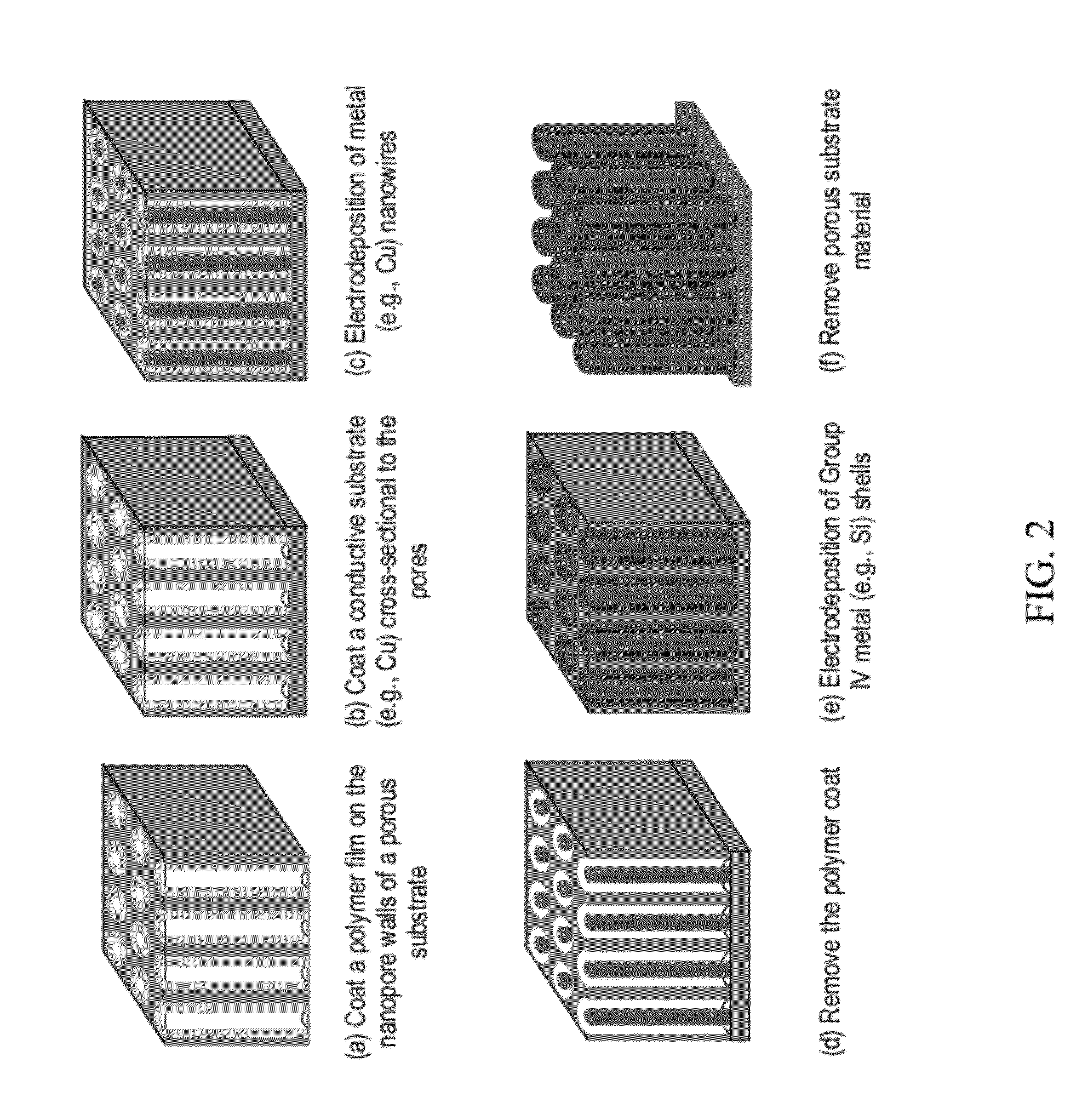
[0014]In an alternative exemplary method for producing the nanowire array composition of the first embodiment described above, the method preferably includes the steps of: (i) depositing a coating of an etchable material into pores of a porous substrate provided that a nanochannel having a width remains in each coated pore; (ii) depositing a transition metal into the nanochannels to produce transition metal nanowires, wherein the transition metal nanowires have widths equivalent or substantially comparable to the nanochannel widths; (iii) removing the coating of etchable material to provide a spacing between each transition metal nanowire and inner walls of the pores of the porous substrate; and (iv) depositing a metal that includes at least one Group IV metal selected from silicon, germanium, and tin, into the spacings to produce an array of (transition metal core)-(Group IV metal shell) nanowires. The foregoing alternative method is particularly useful in providing nanowire arrays with improved uniformity in wire dimensions and alignment.
[0017]The nanowire array compositions described herein can advantageously produce at least the same and higher theoretical capacities when employed in a lithium-ion battery (e.g., 1000-3000 mAh / g), depending on the core and shell compositions, the density of nanowires on the substrate, thicknesses of the nanowires, and numerous other features. Further advantages include a generally improved capacity retention on cycling, as well as maintaining or improving charging, power density, and physical integrity during cycling. The preparative methods described herein also possess numerous advantages including energy efficiency, low cost, scalability, adjustability, and environmental soundness.

Problems solved by technology

Such cracks are generally inevitable due to material flaws and the significant volume change in charge-discharge cycles.

Method used


Image

  • Composite nanowire compositions and methods of synthesis
  • Composite nanowire compositions and methods of synthesis
  • Composite nanowire compositions and methods of synthesis

Examples


example 1

Synthesis of a Cu—Si Core-Shell Nanowire Array

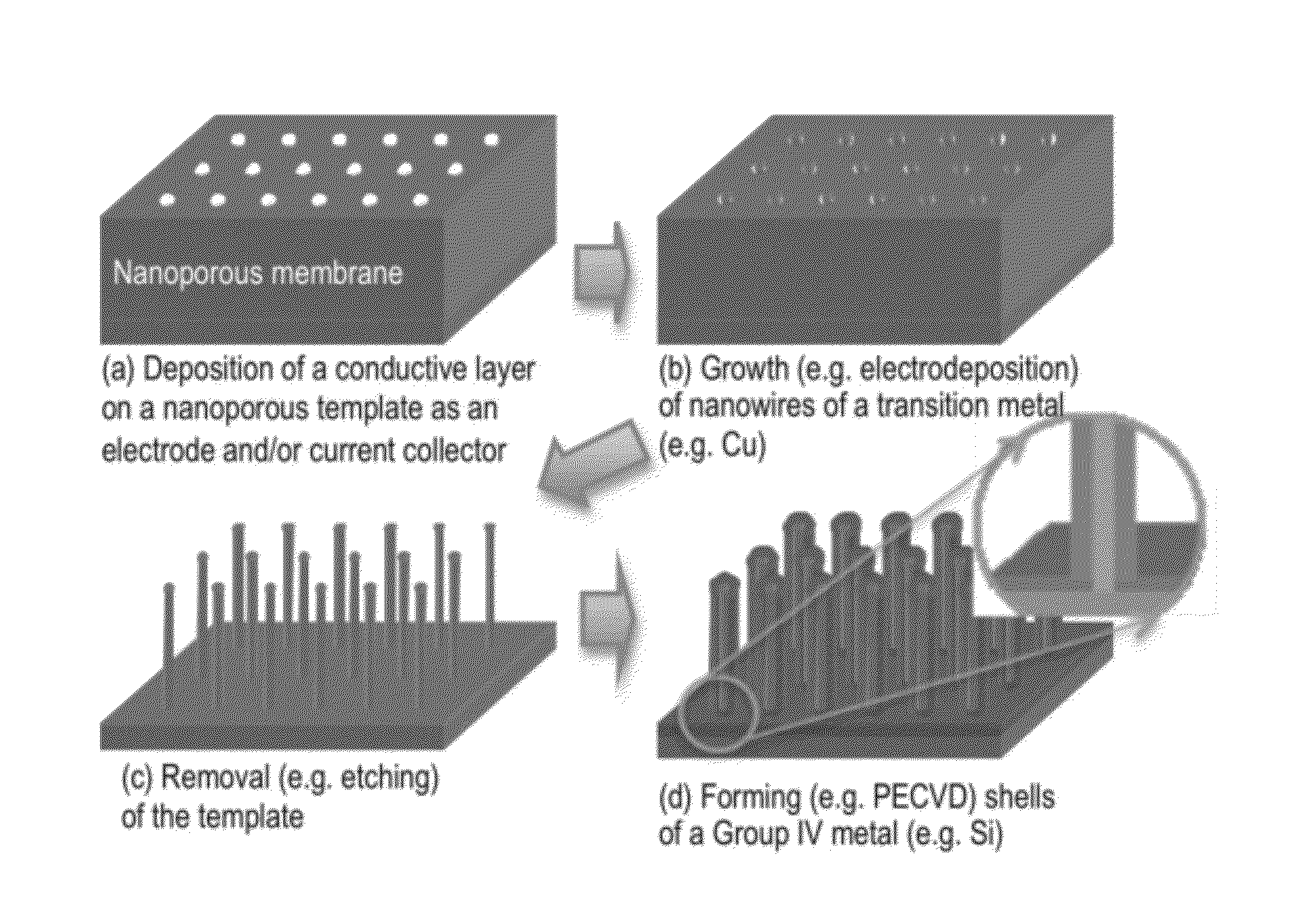
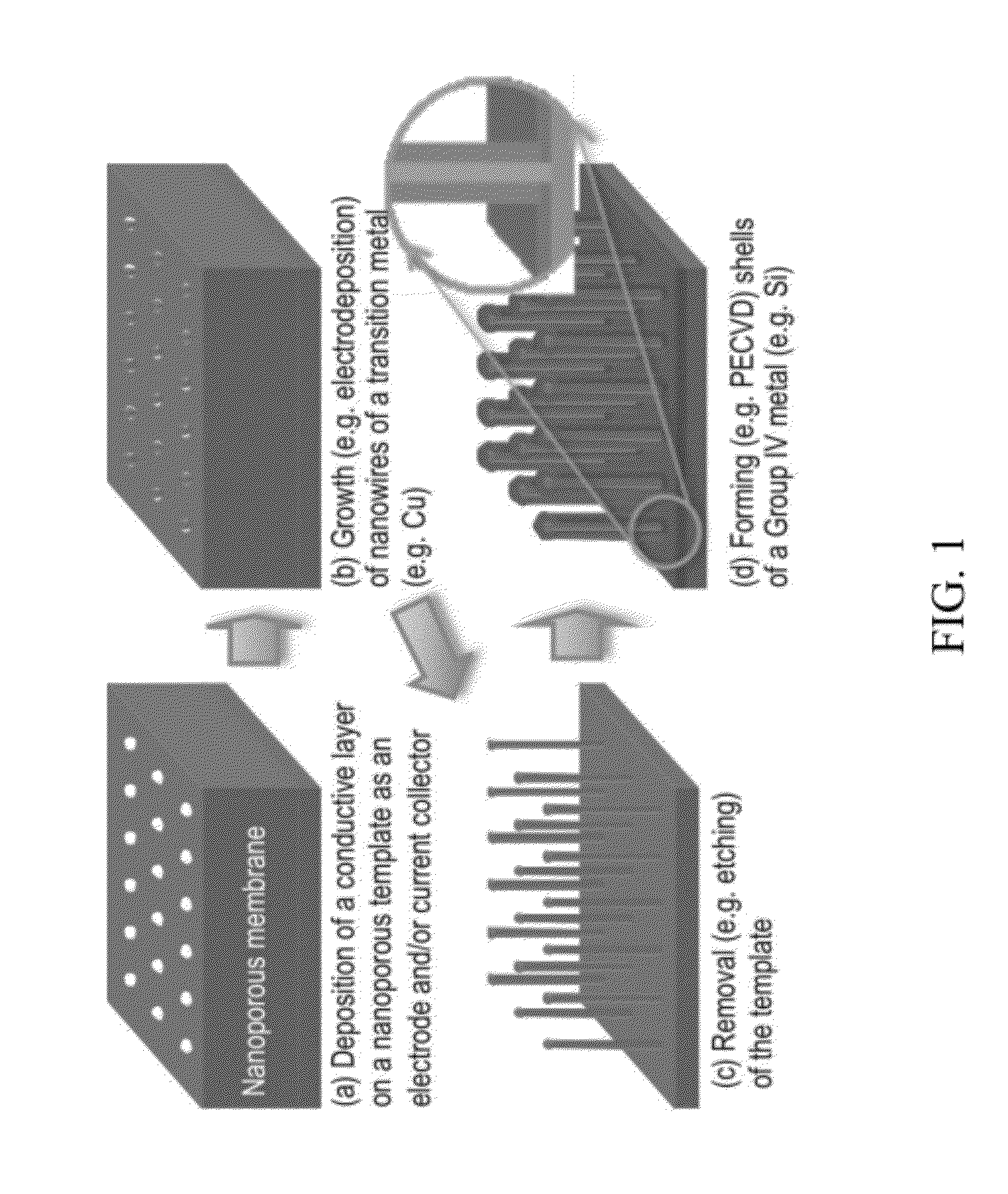
[0085]A Cu—Si core-shell nanowire array was fabricated according to the general schematic shown in FIG. 1 (i.e., by template-aided electrodeposition). A nanoporous polycarbonate (PC) membrane was used as a template. The template had a nominal pore size of 100 nm, a nominal pore density of 4×10⁸ / cm2, and a nominal membrane thickness of 6 μm. Referring to step (a) of FIG. 1, a thin gold film of 50-100 nm thickness (indicated as a bottom layer) was first sputtered on a side (i.e., backside) of the PC membrane using metal evaporation. This gold layer was too thin to cover the pores. Then, a thicker copper backplate (−20 μm) was grown on top of the gold film via electrodeposition. The deposition was conducted using a CHI model 660A potentiostat / galvanostat (CH Instruments, Austin, Tex.) in a three-electrode configuration with a Ag / AgCl reference electrode. The electrolyte was an aqueous solution containing 0.6 M CuSO4 and 1.0 M H2SO4. The app...

example 2

Electrochemical Evaluation of the Cu—Si Core-Shell Nanowire Array as an Anode Material for Lithium-Ion Batteries

[0089]Two-electrode coin-type half-cells were assembled for the Cu—Si core-shell nanowire array, produced according to Example 1, using lithium metal foil as the counter / reference electrode with a polypropylene membrane separator. The electrolyte solutions contained 1.2 M LiPF6 in a 1:2 mixture (by weight percent) of ethylene carbonate (EC) and dimethylcarbonate (DMC). Cells were assembled in glove boxes filled with pure argon. Galvanostatic charge—discharge cycling was performed using a multichannel battery tester from Maccor Inc., model 4000. They were tested in a potential range of 2.0-0.005 V using a constant current charge-discharge protocol at various rates from C / 30 to 10 C. The initial half-cell testing results are described below and shown in FIG. 7.

[0090]The capacity of the Cu—Si core-shell nanowire array was observed to be approximately 1000 mAh / g at a charge / di...


PUM


Abstract

Nanowire array compositions in which nanowires containing at least one Group IV metal (e.g., Si or Ge) in a single layer or core-shell nanowire structure, wherein, in particular embodiments, the nanowires have a transition metal core and / or are surrounded by or embedded within a metal oxide or metal oxide-ionic liquid ordered host material. The nanowire compositions are incorporated into the anodes of lithium ion batteries. Methods of preparing the nanowire compositions, particularly by low temperature methods, are also described.

Description

[0001]This invention was made with government support under Contract Number DE-AC05-00OR22725 between the United States Department of Energy and UT-Battelle, LLC. The U.S. government has certain rights in this invention.FIELD OF THE INVENTION[0002]The present invention relates, generally, to core-shell nanowire compositions, as well as materials useful as anodes for lithium ion batteries.BACKGROUND OF THE INVENTION[0003]Current lithium-ion battery capacity (as used in, for example, electric vehicles) is mainly limited by the low theoretical capacity (372 mAh / g) of the graphite anode. Among known anode materials, silicon (Si) has the highest theoretical capacity i.e., 4,200 mAh / g, which is more than ten times higher than that of graphite. However, silicon experiences a very large volume expansion (up to 400%) upon insertion of Li+ during charging, with each silicon atom alloying with an average of 4.4 Li atoms. The significant stresses, thus generated, make silicon anodes vulnerable ...

Claims


Application Information

Patent Timeline
IPC IPC(8): H01M10/056H01M10/058B05D5/12H01B5/14H01M4/58B82Y99/00
CPCB01J13/02B82Y30/00Y02E60/122H01M4/386H01M4/134Y02E60/10Y02P70/50
Inventor QU, JUNDAI, SHENG
Owner UT BATTELLE LLC
Learn More